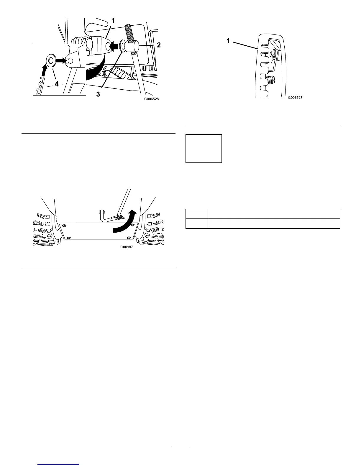
Figure12
1.Speedselectorlever
3.Innerwasher
2.Trunnion
4.Outerwasher
Note:Tomakeinstallationeasier,leavetheatwasher
onthetrunnion(Figure12).
4.ShiftthespeedselectorleverintoPositionR2.
5.Rotatethelowerlinkarmfullyupward
(counterclockwise)(Figure13).
Figure13
6.Liftuponthespeedcontrolrodandinsertthetrunnion
intotheholeinthespeedselectorlever(Figure12).
Note:Ifthetrunniondoesnottintothehole
whenyouliftuponthespeedcontrolrod,rotatethe
trunnionupwardordownwardonthespeedcontrol
roduntilitts.
7.Securethetrunnionandupperendofthespeedcontrol
rodwiththeouterwasherandahairpincotteryou
previouslyremoved.
Note:Foreasierinstallation,lookdownthroughthe
openinginthespeedselector(Figure14).
Figure14
1.Speedselector
4
InstallingtheChuteControl
Rod
Partsneededforthisprocedure:
2
Carriagebolts
2Locknuts
Procedure
1.UnwraptheQuickStickandrotateitsothatitis
uprightandinthecenter.
2.Holdthebluetriggercapdownandpulltheleverfully
rearward.
Note:Thedischargechuteanddeectorshouldface
forward.Iftheydonot,holdthebluetriggercap
down(butdonotmovetheQuickStick)androtatethe
dischargechuteuntiltheydo.
3.Aligntheattenedbackendofthelongchutecontrol
rodwiththeattenedfrontendoftheshortrod
thatextendsfromthecontrolpanelsothattheynest
together(Figure15).
10
 Loading...