9.Loopthediggingchainovertheaugerdriveshaftand
ontothedrivesprocket,ensuringthatthedigging
teethpointforwardontheupperspan.
10.Settheupperspanofthechainintoplaceonthe
trencherboom,thenwrapthechainaroundthe
rollerattheendoftheboom.
11.Threadtheadjustmentboltintotheboomandturn
itinuntilthereis1-1/2to2-1/2inches(3.8to6.3
cm)ofslackinthechainonthebottomspan.
12.Threadthejamnutdowntheadjustingboltand
tightenitsecurelyagainsttheboom.
13.Torquethe2boltsandnutssecuringtheboomto
135to165ft-lb(183to223N-m).
14.Installthespoilsaugerusingthebolt,2saddle
washer,andnutyouremovedpreviously.
15.Torquetheboltandnutto75ft-lb(101N-m).
2
CheckingFluidLevels
NoPartsRequired
Procedure
Beforestartingtheengineforthersttime,checkthe
engineoilandhydraulicuidlevels;refertoOperation
formoreinformation.
3
ChargingtheBattery(Electric
StartModelsOnly)
NoPartsRequired
Procedure
Chargethebattery;refertoServicingtheBatteryin
Maintenanceformoreinformation.
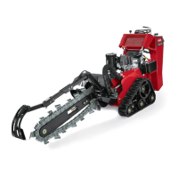
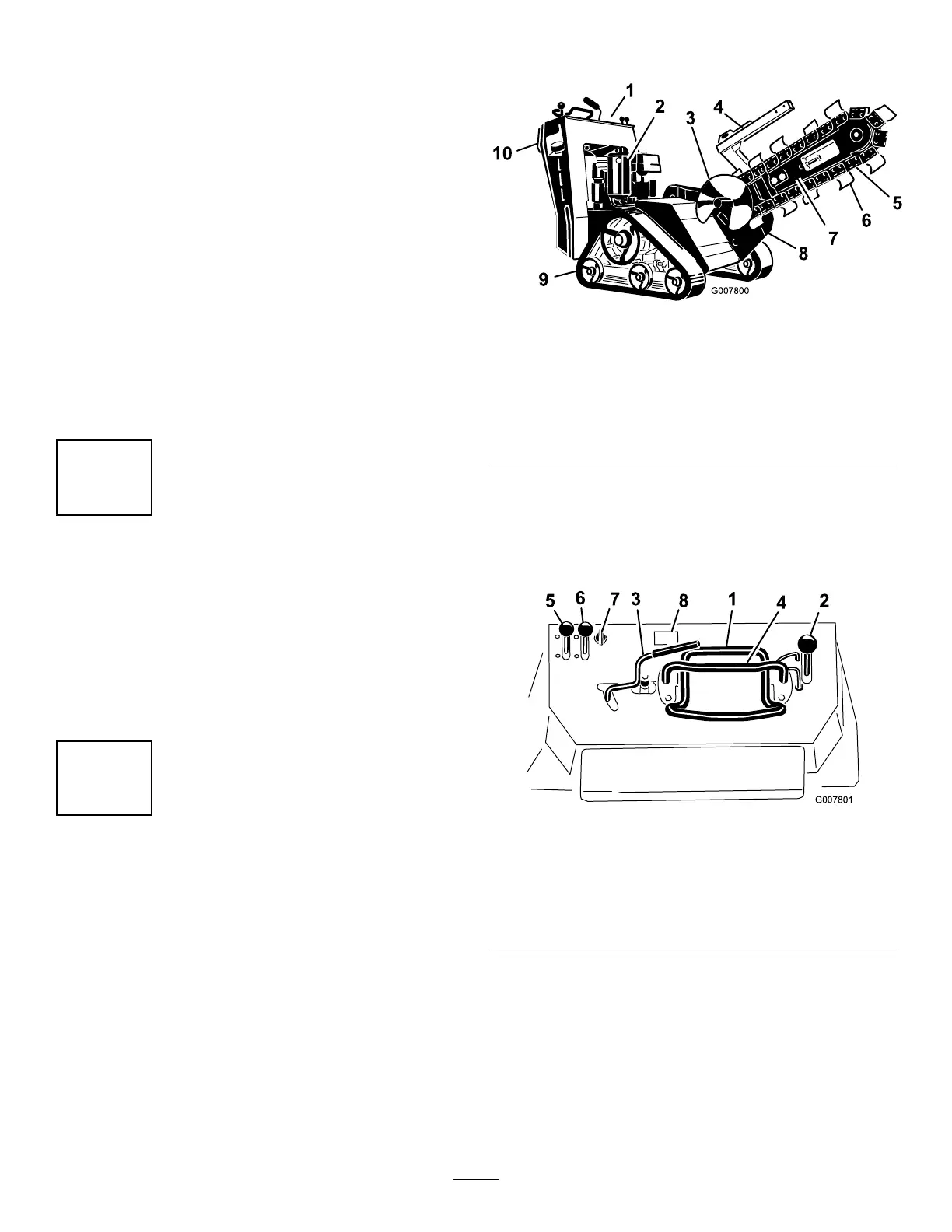
ProductOverview
Figure4
1.Control
panel
4.Chain
guard
7.Boom10.Reverse
safety
plate
2.Engine
5.Chain
8.Trencher
head
3.Spoils
auger
6.Digging
teeth
9.Track
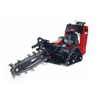
Controls
Becomefamiliarwithallthecontrols(Figure5)before
youstarttheengineandoperatethemachine.
Figure5
1.Tractioncontrol5.Throttlelever
2.Boomelevationlever
6.Chokelever
3.Trenchercontrollever7.Keyswitch
4.Referencebar8.Hourmeter(optional
accessoryonmodel
22970)
KeySwitch,Model22970
Thekeyswitchhas2positions:offandrun.
Tostarttheengine,rotatethekeytotherunposition,
thenpulltherecoilhandleontheengine.
Tostoptheengine,rotatethekeytotheoffposition.
13
 Loading...