2
TOSHIBA 2857 DB
Item Name Setting(User control) Input signal Measurement point Adjustment procedure Adjustment standard
[COLP] SUB Contrast: MAX Sub-bright IC501 1. Select slave address OCH 1.35V(p-p)
COLOUR Bright: CENTER signal #55 [COLP]. ± 0.2V(p-p)
PAL Color: CENTER (PAL) (TP501) 2. When [COLP] is selected, Y-signal is muted
and only color signals are outputted.
3. Adjust amplitude of the upper half of the colour
bar output.
[RCUT] R cut-off RCUT 40 Hexa-decimal Screen 1. Set the controls as shown in
[GCUT] G cut-off GCUT 40 Hexa-decimal adjustment the left column.
[BCUT] B cut-off BCUT 40 Hexa-decimal 2. Gradually increase the screen
Screen VR Screen GDRV 40 Hexa-decimal VR (T461) until one of R, G or BDRV B line begins
Select horizontal line mode by to brighten slightly.
pressing
-I-
- button on the remote 3. Determine the position of the screen VR here.
control in service mode. 4. Adjust RCUT, GCUT and BCUT, brighten other lines
until they begin to light slightly.
(Adjust DATA so that the line becomes almost white.)
5. Press
-I-
- button on the remote control to escape from the
horizontal line mode.
[RCUT] R cut-off Contrast: MAX White, etc. Screen 1. This adjustment must be done HIGH LIGHT;
[GCUT] G cut-off Bright : CENTER adjustment after adjustment of the above- (103cd/m
3
)
[BCUT] B cut-off Color : CENTER mentioned cut-off and screen 7195K
[GDRV] C drive VR’s have been completed. -0.005uv [BDRV]
[BDRV] B drive 2. Adjust cut-off and drive DATA DARK;
(White alternately. (17cd/m
3
)
balance) 3. Use a checker to adjust 7695K ± 0uv
brightness by changing modulation factor.
ITEM:
Initialisation of QA02 (Memory)
ADJUSTMENT PROCEDURE:
After replacing QA02, the following initialisation
is required.
1. Call up the adjustment mode display following
the steps 1 and 2.
2. Press the CALL button on the Remote Control
and CHANNEL ▲ buttons on the TV set
simultaneously. The initialisation of QA02 has
been completed.
3. Check the picture carefully. If necessary,
adjust any adjustment item.
Perform “AUTOMATIC SEARCH MEMORY”
ITEM: SUB-BRIGHTNESS (Address: BRTC)
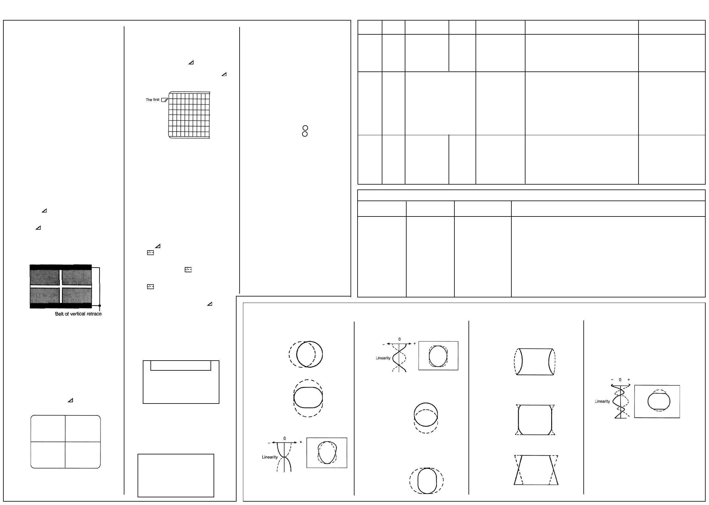
Note: Constrict the picture height until the
vertical retrace line appears adjusting the
address HIT (HEIGHT).
ADJUSTMENT PROCEDURE:
1. Set CONTRAST to “00,, and BRIGHTNESS to
“50” by adjusting user controls.
2. Set the TV in service mode to get white cross-
bar of inside pattern.
3. Select BRTC (brightness correction), and
adjust the - / + button to reduce the value
so that white portion of inside pattern slightly
light.
4. Adjust - / + button to increase the data
value of BRTC, and set it just before the
difference between the belt of vertical retrace
and the border of black portion of inside
pattern is visible. After that, return vertical
height and contrast.
ITEMS:
HORIZONTAL POSITION ADJUSTMENT
(HPOS)
VERTICAL POSITION ADJUSTMENT (VPOS)
ADJUSTMENT PROCEDURE:
1. Set the TV in service mode, and get black or
white cross-bar signal with VIDEO button on
remote hand unit.
2. Select either HPOS (Horizontal picture phase)
or VPOS (Vertical picture phase) with
CHANNEL ▲, ▼ buttons, and adjust horizon-
tal or vertical picture position in the center of
screen with VOLUME - / + buttons.
ITEM:
VERTICAL AMPLITUDE ADJUSTMENT (HIT)
ADJUSTMENT PROCEDURE:
1. Set the TV in service mode, and get black or
white cross-hatch signal with VIDEO button
on remote hand unit.
2. Select HIT (Vertical amplitude) with CHAN-
NEL ▲, ▼ buttons, and adjust vertical
amplitude with VOLUME - / + buttons so
that vertical amplitude lacks a little.
3. Adjust vertical amplitude with VOLUME - /
+ buttons so that the first bar on cross-hatch
signal touches edge of screen.
WHITE BALANCE ADJUSTMENT
CUTOFF ADJUSTMENT
(RCUT)
(GCUT)
(BCUT)
DRIVE ADJUSTMENT
(GDRV)
(BDRV)
1. Set Contrast to 40, and brightness to +20 by
picture control.
2. Set the TV in service mode, and get the inside
W/B adjusting signal with VIDEO button.
3. Select RCUT, GCUT and BCUT with CHAN-
NEL ▲, ▼ buttons, to set individual values to
32, and to set GDRV and BDRV to 20 with
VOLUME - / + buttons.
4. Press button on the remote control and
rotate Screen VR to get one slight horizontal
line on screen.
Note:Every pressing of button provides
Horizontal line picture and Normal picture
alternately.
5. Press button to release horizontal line
picture, and select the two other colors which
did not light in the above step with CHANNEL
▲,▼ buttons. Then tap VOLUME - / +
buttons so that three colors slightly light in the
same level.
To correct white balance in light area, select
GDRV and BDRV with CHANNEL ▲,▼ buttons
to adjust.
To correct white balance in dark area, perform
fine adjustment of RCUT, GCUT and BCUT.
Light area check (to show white)
Dark area check (to show black)
SELF DIAGNOSTIC FUNCTION
1) Press “9” button on Remote Control during
display of adjustment menu. The diagnosis
will begin to check if interface among IC’s are
executed properly.
2) During diagnosis, the following displays are
shown.
(SELF CHECK)
(1) 2390XXXX
(2) POWER : 00
(3) BUS LINE : OK
(4) Bus CONT : OK
(5) BLOCK : UV V1 V2
QV01
1) Part number of microcomputer (QA01)
2) Operation number of protecting circuit ----“00”
is normal. When indication is other than “00”,
overcurrent apts to flow, and circuit parts may
possibly be damaged.
3) BUS LINE CHECK ---- “OK” is normal.
“SDA1-GND” means that SDA line is shorted
to ground.
“SCL1-GND” means that SCL line is shorted
to ground.
“SCL1-SDA1” means that SDA line is shorted
to SCL line.
4) BUS CONT----“OK” is normal.
When indication shows “Q OOO NG”, the
device with the number may possibly be
damaged.
5) BLOCK
UV : TV reception mode
V1: VIDEO 1 input mode ( 1)
V2 :VIDEO 2 input mode ( 2)
Indicated color of mode now selected: Green
and Red
Indicated color of other modes: White
Green: Normal
Red: The microcomputer operates to provide
judgement of no video signal. The red color is
still indicated though the signal is input, failure
may exist in input signal line including QV01.
QV01: In case of indication green --- Normal
In case of indication red with input signal ----
Failure may exist in output line including QV01.
➜
➜
Model name: C5SS (2857DB/3357DB)
Adjustment parts or Input point/ Adjustment signal Adjustment conditions and procedures
Bus control item Output point
Horizontal amplitude Visual check of picture WG Philips pattern 1. Conditions: After V. HEIGHT, VERT POSITION
adjustment (WID) (Bus control) and H. CENT have been adjusted, set
Pin distortion Do not use the Philips the controllers as follows:
compensation amount pattern of Contrast: MAX
adjustment (PARA) FRANCESECAM. Brightness: Center
Keystone distortion Color: Center
compensation amount 2. Adjustment procedure
adjustment (HOP) a. Adjust the horizontal amplitude by the sub address WID.
Adjust so that the left and right white flags of
Philips pattern disappear at the very limits.
b. Make the left and right vertical bars straight by the sub address PARA.
c. Compensate the key distortion by the sub address HOP.
d. Again, adjust the sub address WID.
Sub Data Additional Description
Symbol Description
HPOS H screen position correction
HIT V amplitude adjustment.
LIN V linearity correction 1.
Linearity balance between top
and bottom screen.
Symbol Description
VSC V linearity correction 2.
Linearity balance between top/
bottom and center.
VPOS VPS V picture position adjustment
VCP Setting of amount of V amplitude
correction against variation of
screen brightness.
WID H amplitude adjustment.
Symbol Description
PARA H pin-cushion distortion
correction.
CNR H pin-cushion distortion
correction at four corners.
TRAP Pedestal distortion correction.
Symbol Description
HCP Setting of amount of H amplitude
correction against variation of
screen brightness.
VFC V linearity correction.
Linearity balance at 1/4, 3/4
areas from top.
Service Mode Cont’d
 Loading...