1.1 Wall Mounting Preparation
Before mounting the device, you need to prepare the tools below:
Ǵ A screw driver.
Ǵ Two screws which complies to the corresponding standard. For details, see Wall
Mounting Specification.
1.2 Wall Mounting Procedure
On the bottom of the panel, there are two mounting holes. You need to drive two screws
into the wall, then mount the device on the wall. Note that the device should be mounted
on the wall upright rather than sideways.
1) Determine the location on the wall where you want to mount the device.
2) Mark the wall where the two mounting holes are. The distance between the two marks
must be the same as that between the two mounting holes of the device. For the wall-
mounting-holes distance, see Wall Mounting Specification.
3) Drive the screws into the wall at the marks using the screw driver. For the Screw-
Head-to-Wall Minimum Distance, see Wall Mounting Specification.
4) Mount the device on the wall.
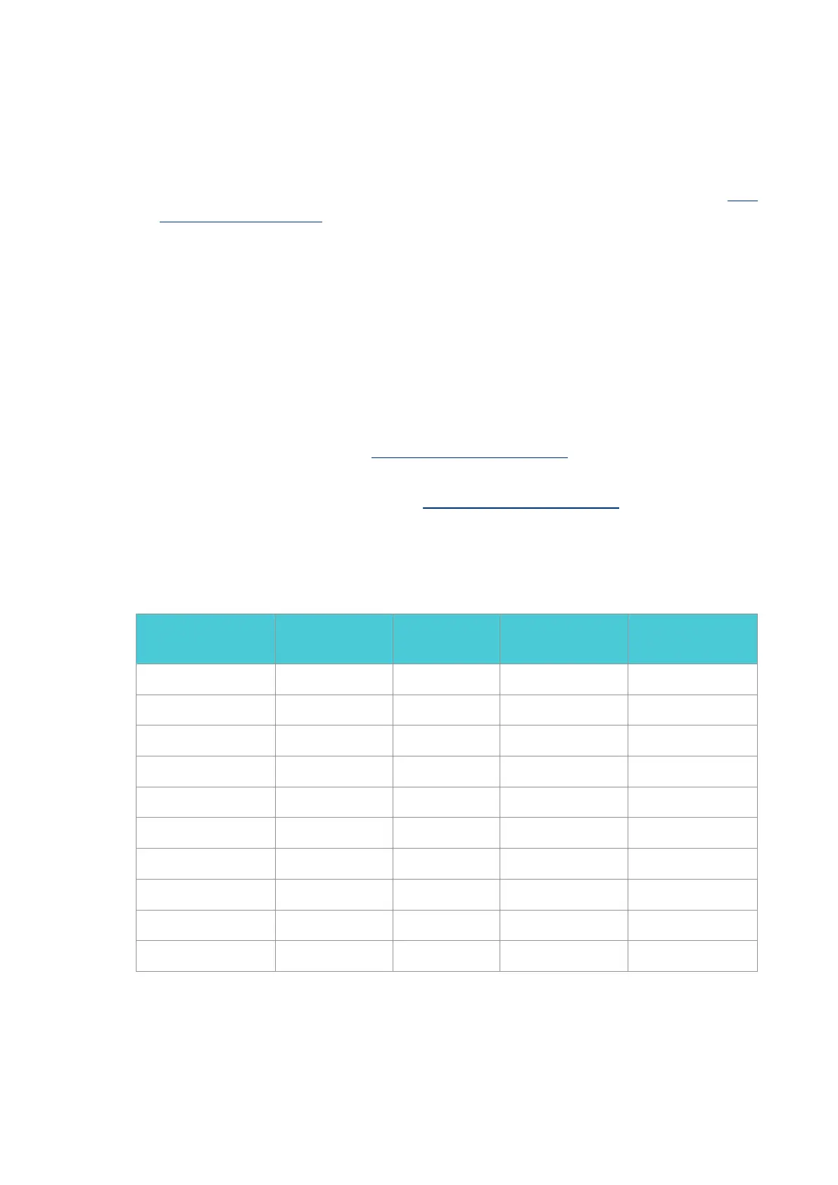
1.3 Wall Mounting Specification
Model
Screw Standard of
ANSI B1.1
Minimum Length
of Screw
Screw-Head-to-Wall
Minimum Distance
Wall-Mounting-Holes
Distance
G36 4# (5#) 6# 7mm 1.5mm 150mm
ER7212PC 4# (5#) 6# 7mm 1.5mm 150mm
ER706W 4# (5#) 6# 7mm 1.5mm 150mm
ER7206 4# (5#) 6# 7mm 1.5mm 150mm
ER707-M2 4# (5#) 6# 7mm 1.5mm 150mm
ER605W 4# 6# 8# 9.7mm 3mm 161.85mm
ER605 4# (5#) 6# 7mm 1.5mm 122mm
Festa FR365 4# (5#) 6# 7mm 1.5mm 150mm
Festa FR205 4# (5#) 6# 7mm 1.5mm 122mm
TL-R470T+ 4# 5# 6# 8.5mm 1.5mm 110mm
 Loading...