Quick Installation Guide
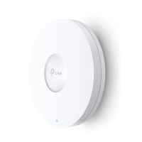
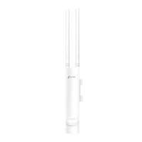
EAP225/EAP245
LED Indication
Interface Panel
The EAP can be ceiling-mounted, or wall-mounted. Follow the steps below for the appropriate
installation.
Wireless Access Point
Option 1: Ceiling Mounting
To remove the EAP from the mounting bracket, insert a paper clip in the Security Slot to
release the Locking Tab and rotate the EAP until it is detached from the mounting bracket, as
shown below.
Tip:
Security Slot
Locking Tab
Note: Make sure that the ceiling tile is bigger than the EAP.
2
Place the mounting bracket in the center of the
ceiling tile. Mark three positions for the screw holes
and a position for the Ethernet cable hole.
Drill three 4mm diameter holes for the screws and a
25mm diameter hole for the Ethernet cable at the
marked positions.
1
Remove the ceiling tile.
3
Secure the mounting bracket to the ceiling tile
using three M3x30 pan-head screws, washers and
wing nuts, as shown on the left.
4
Feed the Ethernet cable through the hole
and set the ceiling tile back into place.
5
Connect the Ethernet cable to the ETHERNET port.
Attach the EAP to the mounting bracket by aligning
the arrow mark on the EAP with the arrow mark
on the mounting bracket, then rotate the EAP until
it locks into place, as shown on the left.
Wing Nuts (Qty.3)Washers (Qty.3) M3×30 Pan-head Screws (Qty.3)
Option 2: Wall Mounting
2
Insert the plastic wall anchors into the 6mm
diameter holes.
Note: For security reasons, it is not recommended to install the EAP with the louver downward.
3
Secure the mounting bracket to the wall by driving
the self-tapping screws into the anchors. Make
sure that the shoulders of the mounting bracket
are on the outside.
4
Connect the Ethernet cable to the Ethernet port
on the EAP.
5
Attach the EAP to the mounting bracket by
aligning the arrow mark on the EAP with the
arrow mark on the mounting bracket, then rotate
the EAP until it locks into place, as shown on the
left.
1
M3×20 Self-tapping Screws (Qty.3)
M3×28 Plastic Wall Anchors (Qty.3)
Hardware Installation
Drill Hole for Ethernet cable
X3
Option 1: Ceiling Mounting Option 2: Wall Mounting
If your Ethernet cable feeds through the wall, you
can position the mounting bracket to make the
cable through the fixing hole. Mark three positions
for the screw holes and then drill three 6mm
diameter holes at the marked positions.
X3
Note: EAP245 is used as an example throughout this guide. EAP225 diers in appearance.
The port is used to connect to the PoE port of the provided PoE adapter or a PSE (Power
Sourcing Equipment), such as a PoE switch, for both data transmission and Power over
Ethernet (PoE) through Ethernet cable.
ETH1 (PoE)
The port is a Gigabit Ethernet port used for bridging.
ETH2 (Only for EAP245)
With the device powered on, press and hold the button for about 5 seconds until
the LED flashes, then release the button. The device will restore to factory default
settings.
RESET
The device is working properly.
Solid Green
The device is working abnormally.
Flashing Yellow Continuously
The device is being reset to its factory
default settings.
Flashes Yellow Once
Flashing Green Then Yellow
The device is updating. Do not
disconnect or power o the device.
For EAP245: For EAP225:
The device is working abnormally.
Flashing Red Continuously
Flashing Yellow
The device is updating. Do not
disconnect or power o the device.
The device is working properly.
Solid Green
The device is being reset to its factory
default settings.
Double-ashing Red, Green then Yellow