4
Chapter 2 Identifying External Components
This chapter describes the front panel and rear panel of the switch.
2.1 Front Panel
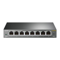
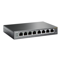
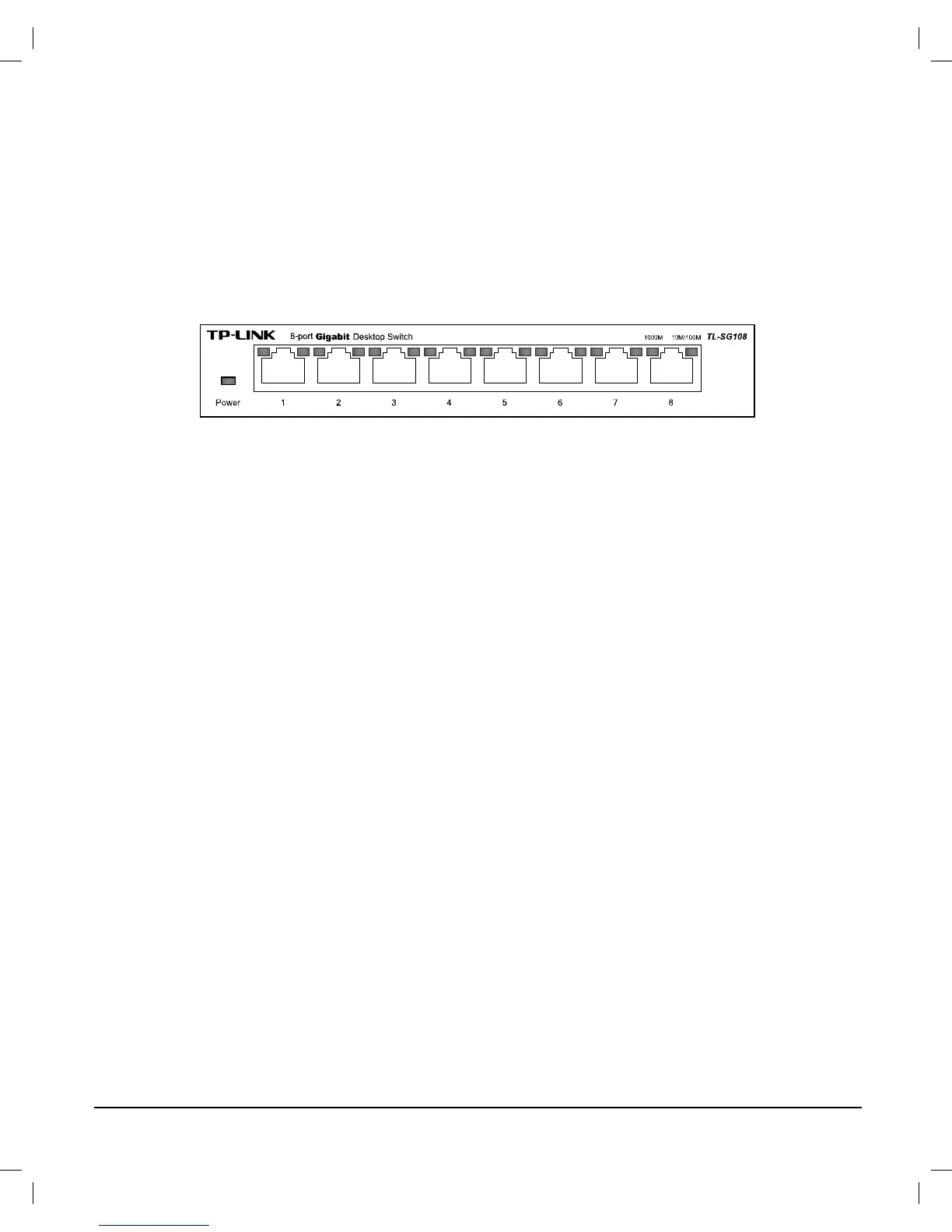
Figure 2-1 TL-SG108 Switch Front Panel
The following parts are located on the front panel:
Ports (1-8): The TL-SG108 switch is equipped with 8 10/100/
1000Mbps Auto-Sensing RJ45 ports where you will connect your
network devices. The working status can be indicated by the
corresponding LEDs on the panel.
Power LED: This indicator will light up when the switch powers on.
LEDs: Each 10/100/1000Mbps Auto-Sensing RJ45 port has two
corresponding LEDs.
The LED on the left side of the RJ45 port will light solid green when a
1000Mbps device is connected to the port. It flashes green when data is
being transmitted or received on the working connection.
The LED on the right side will light solid yellow when a 10/100Mbps
device is connected to the port. It flashes yellow when data is being
transmitted or received on the working connection.
Note:
The LEDs’ description above explains the device’s working status after
initialization.
 Loading...