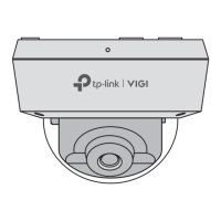
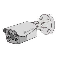
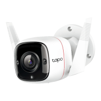
Appearance
Power Supply Interface
(12V DC)
RJ45 Ethernet Port
(supports PoE)
Micro SD Slot*
IR LED
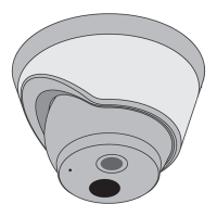
Top Cover
Side Screws
Microphone
Reset Button*
Press for 5 seconds to reset the
camera to factory settings.
Loosen to remove the top cover.
Micro SD Reset
Quick Start Guide
*Images may dier from actual products.
Package Contents
Network Camera
Quick Start Guide
Anchors & Screws
Quick
Start
Guide
•
Make sure your power supply matches your camera. The
camera’s standard power supply is 12V DC or PoE
(802.3af/at). The power source should comply with Power
Source Class 2 ( PS2) or Limited Power Source(LPS) of IEC
62368-1.
• Make sure that the wall is strong enough to withstand 4
times the weight of the camera and mounting bracket.
• If you are uncertain or uncomfortable performing the
installation, consult a qualied electrician.
Safety First:
Mounting Template
2. Decide how to route the cable through the ceiling/wall. 4. Rotate the lens base or the dome to adjust the angle of the
lens as desired. Tighten the side screws to secure the cover.
1. Loosen the screws on the side of the camera to remove
the top cover.
3. Stick the mounting template to the desired mounting place,
and mount the camera. Pay attention to the cable direction.
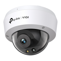
Dome Network Camera
Mounting Template
Anchor
Reinstall the top cover
Adjust lens angle
Mount the camera
Remove the top cover
Ceiling or Wall
Route the cable through the
bottom of the camera
Knock out the cable hole on the side
and route the cable from the side
Self-tapping Screw
*Some models do not have the SD slot and reset button. You can check the detailed
specications on the product page at https://www.tp-link.com/.
Camera
Ceiling or Wall
Waterproof Cable
Attachments
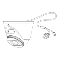
Installing Waterproof Cable Attachments
Install the waterproof cable attachments for the network interface when the
camera is installed outdoors.
Note: Make sure each part is securely attached and the waterproof rings are
ush to keep out water.
Done! The network interface is now waterproof.
Fix Nut
Waterproof
Ring
O-ring
Network
Interface
Waterproof
Jacket
1. Route the network cable through the following components in order: x
nut, waterproof ring, and then the waterproof jacket.
2. Fix the O-ring to the network interface of the camera and connect the
network cables.
3. Attach the network interface with the waterproof jacket, then twist to
lock.
4. Insert the waterproof ring into the waterproof jacket. Rotate the x nut
to secure it to the waterproof jacket.
White LED