8
88-4TCA4001-1C-EN
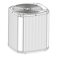
Step 4 — Unit Installation
NNoottee:: The factory ships this unit for horizontal
installation.
TToo IInnssttaallll tthhee uunniitt aatt ggrroouunndd lleevveell::
1. Place the unit on a pad the size of the unit or larger.
The unit must be mounted level for proper drainage
of water through the holes in the base pan. To
attach the unit securely to the slab, use extreme
mounting kit, BAYEXMK003A.
The pad must not come in contact with the
structure. Be sure the outdoor portion of the supply
and return air ducts are as short as possible.
2. Location of the unit must allow service clearance
around it. Clearance of the unit must be given
careful consideration. See Figures 1 to 6.
NNoottee:: Any reduction of the unit clearances indicated
in these illustrations may result in condenser
coil starvation or the recirculation of warm
condenser air. Actual clearances, which
appear to be inadequate should be reviewed
with a local engineer.
3. Attach the supply and return air ducts to the unit as
explained in the ductwork Installation section.
4. Flexible duct connectors must be of a flame
retardant material. Insulate any ductwork outside of
the structure with at least two (2) inches of
insulation and weatherproof. There must be a
weatherproof seal where the duct enters the
structure.
5. Do not expose the unit to direct roof water runoff.
6. Seal all holes through exterior walls in accordance
with local codes.
7. Continue with the following installation sections to
complete the installation: Ductwork, Filter and
Electrical Wiring.
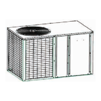
RRooooffttoopp IInnssttaallllaattiioonn —— CCuurrbb MMoouunnttiinngg
CCoonnvveerrtt HHoorriizzoonnttaall AAiirrffllooww ttoo DDoowwnn AAiirrffllooww
The factory ships the unit for horizontal airflow.
Perform this procedure to convert it to down airflow:
1. Remove the three (3) sheet metal screws securing
the supply air cover and the four (4) sheet metal
screws securing the return air cover from the base
of the unit. Remove the covers from the base.
2. Place the covers over the horizontal supply and
return openings (painted side out). Align the screw
holes, and secure using the same screws removed
in step 1.
IInnssttaallll FFuullll PPeerriimmeetteerr RRooooff MMoouunnttiinngg CCuurrbb
1. Verify that the roof mounting curb is correct for the
unit. There are two curbs depending on the unit
cabinet sizes:
• Use model BAYCURB060A
2. Assemble and install the curb following the
instructions in the Installer's Guide included with
the appropriate curb.
 Loading...