16
18-BC98D1-1G-EN
Electrical — Low Voltage Non Communicating
Table 20. Low Voltage Maximum Wire Length
The table defines the maximum total length of low voltage wiring
from the outdoor unit, to the indoor unit, and to the thermostat.
Note: The use of color coded low voltage wire is recommended to
simplify connections between the outdoor unit, the control,
and the indoor unit.
24 VOLTS
WIRE SIZE MAX. WIRE LENGTH
18 AWG 150 Ft
16 AWG 225 Ft.
14 AWG 300 Ft.
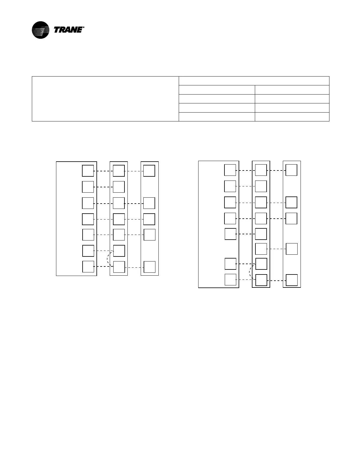
Low Voltage Hook-up Diagrams
With TEM 3, 4, 6, 8
Thermostat Air Handler
Outdoor
Unit
R
G
B
W1
W2
R
B
O
Y
X2
R
G
B/C
O
Y
W
Blue
24 VAC HOT
FAN
24 VAC
Common
SOV
COOL/HEAT
1st STAGE
HEATING
2nd STAGE
EMERGENCY
HEAT
Pink Black
White
X2
O
Y*
With TAM 4, 5, 7, 9
Thermostat Air Handler
Outdoor
Unit
R
G
B
W1
W2
R
B
O
Y
O
Y
O
X2
R
G
B/C
O
Y
l
W
Blue
O
Y
l
24 VAC HOT
FAN
24 VAC
Common
SOV
COOL/HEAT
1st STAGE
HEATING
2nd STAGE
EMERGENCY
HEAT
Pink Black
White
X2
•
Units with pigtails require wirenuts for connections.
•
In AC systems for multiple stages of electric heat, jumper W1 and W2 together if comfort control has only one stage of heat.
* Y2 for TEM6
 Loading...