18-AC78D1-6 13
Notes:
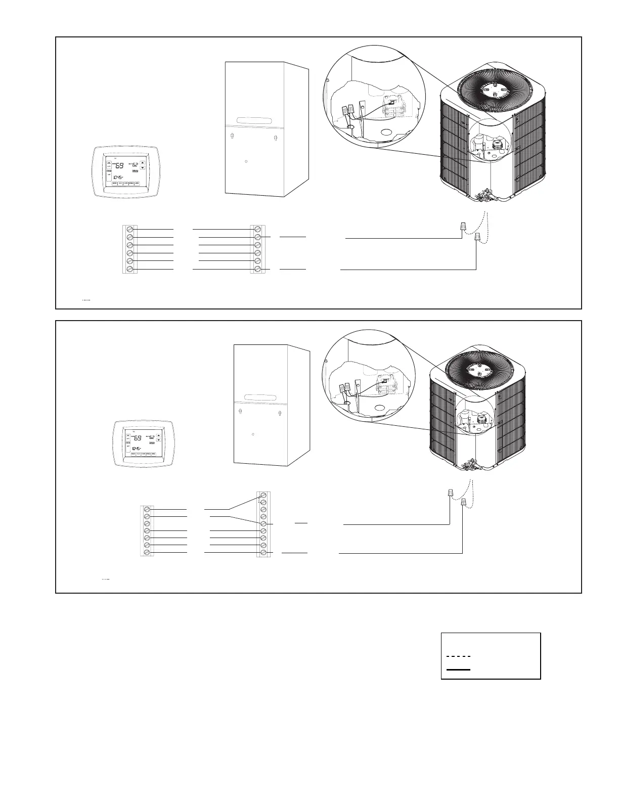
1. Be sure power supply agrees with equipment nameplate.
2. Power wiring and grounding of equipment must comply with local codes.
3. Low voltage wiring to be No. 18 AWG minimum conductor.
4. ODT-B must be set lower than ODT-A.
5. If outdoor thermostats (ODT) are not used, connect W1 to W2 and W3.
LEGEND
FACTORY WIRING
FIELD WIRING
Hook-up Diagram
Yellow
Green
White
Black
W2*
B - Blue
Blue
W1
Blue
B
W1
W2
G
G
Y
Y - Yellow
B
Y
Yellow
Low Voltage connection
must be made inside the
outdoor unit case.
R
Red
Yellow
Green
White
Black
Blue
R
Red
* W2 is present only on 2 stage comfort control and furnace
Factory wiring
Comfort Control
1 or 2 Stage Gas Furnace
Air Conditioner
Variable Speed Gas Furnace
Hook-up Diagram
Red
Yellow
Green
White
Black
Blue
Yellow
Green
White
Black
W2*
* W2 is present only on 2 stage comfort control and furnace
Factory wiring
B - Blue
Blue
W1
Blue
B
W1
W2
G
G
Y2
Y/Y2
Yellow
Y1
Y - Yellow
B
O
BK
Y
LO
/Y1
Yellow
Low Voltage connection
must be made inside the
outdoor unit case.
Comfort Control
Variable Speed Gas Furnace
Air Conditioner
R
R
Red
 Loading...