18-AC51D1-10F-EN 15
1. Leak check refrigerant lines. ........................................ [ ]
2. Properly insulate suction lines and fittings. ................... [ ]
3. Properly secure and isolate all refrigerant lines. ........... [ ]
4. Seal passages through masonry.
If mortar is used, prevent mortar from coming
into direct contact with copper tubing. .......................... [ ]
5. Verify that all electrical connections are tight. ............... [ ]
6. Observe outdoor fan during on cycle for clearance
and smooth operation. .................................................. [ ]
Section 15. Checkout Procedures
15.1 Operational And Checkout Procedures
CHECKOUT PROCEDURE
After installation has been completed, it is recommended that the entire system be checked against the following list:
Final phases of this installation are the unit Operational and Checkout Procedures. To obtain proper performance, all units
must be operated and charge adjustments made.
Important: Perform a final unit inspection to be sure that factory tubing has not shifted during shipment. Adjust tubing if
necessary so tubes do not rub against each other when the unit runs. Also be sure that wiring connections are tight and
properly secured.
7. Be sure that indoor coil drain line drains freely. Pour water
into drain pan. ............................................................... [ ]
8. Be sure that supply registers and return grilles are open
and unobstructed. ......................................................... [ ]
9. Be sure that a return air filter is installed. ..................... [ ]
10. Be sure that the correct airflow setting is used.
(Indoor blower motor) ................................................... [ ]
11. Operate complete system in each mode to
ensure safe operation. .................................................. [ ]
PRINTED FROM D157394P01
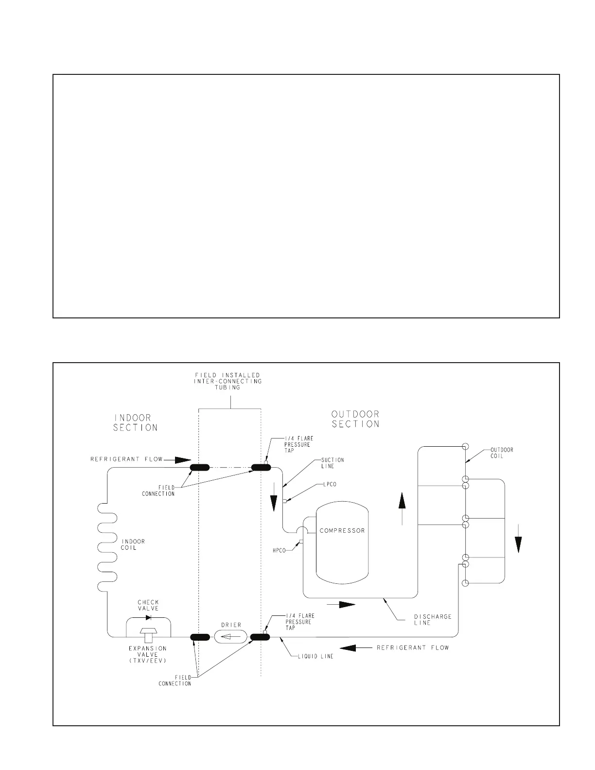
NOTE: 4TTR4049N1000A does not have a sub-cooling circuit.
Section 16. Refrigerant Circuits (Reference only)
 Loading...