18-AC51D1-8-EN 21
STEP 8 - Verify typical performance.
Refer to System Pressure Curves in the Service
Facts to verify typical performance.
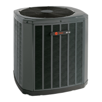
STEP 6 - Adjust refrigerant level to attain
proper gage pressure.
Add refrigerant if the Liquid Gage Pressure
is lower than the chart value.
1. Connect gages to refrigerant bottle
and unit as illustrated.
2. Purge all hoses.
3. Open bottle.
4. Stop adding refrigerant when liquid
line temperature and Liquid Gage
Pressure matches the charging chart
Final Subcooling value.
Recover refrigerant if the Liquid Gage Pres-
sure is higher than the chart value.
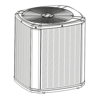
20 MIN.
STEP 7 - Stabilize the system.
1. Wait 20 minutes for the system condi-
tion to stabilize between adjustments.
Note: When the Liquid Line Temperature and
Gage Pressure approximately match the chart,
the system is properly charged.
2. Remove gages.
3. Replace service port caps to prevent
leaks. Tighten finger tight plus an ad-
ditional 1/6 turn.
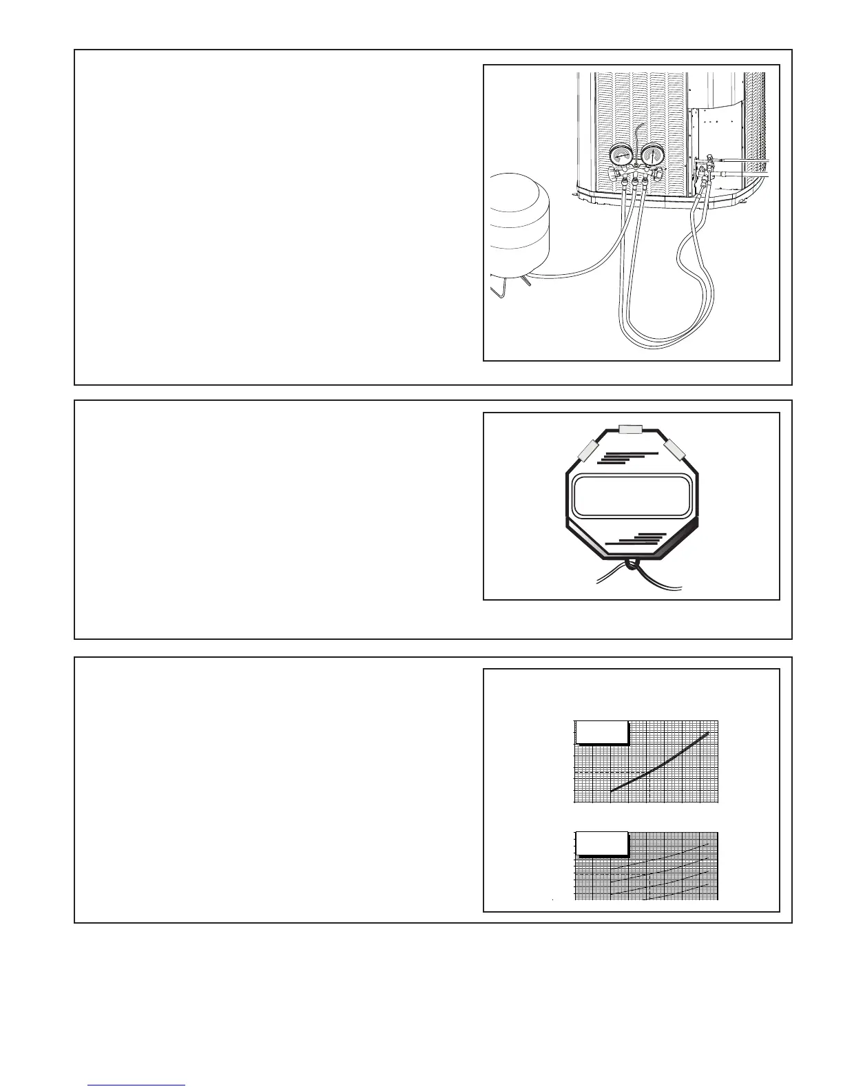
(Example only - see Service Facts)
PRESSURE CURVES FOR 4TTX5049E1
4TXCD010CC3
Cooling @ 1400 CFM
LIQUID PRESSURE (PSIG)
OUTDOOR TEMPERATURE (Degree F)
N PRESSURE (PSIG)
OUTDOOR TEMPERATURE (Degree F)
COOLING PERFORMANCE CAN BE CHECKED WHEN THE OUTDOOR TEMP IS ABOVE 65 DEG F.
TO CHECK COOLING PERFORMANCE, SELECT THE PROPER INDOOR CFM, ALLOW PRESSURES TO STABILIZE. MEASURE INDOOR WET BULB
TEMPERATURE, OUTDOOR TEMPERATURE, LIQUID AND SUCTION PRESSURES. ON THE PLOTS LOCATE OUTDOOR TEMPERATURE (1);
LOCATE INDOOR WET BULB (2); FIND INTERSECTION OF OD TEMP. & ID W.B. (3); READ LIQUID (4) OR SUCTION (5) PRESSURE IN LEFT COLUMN .
EXAMPLE: (1) OUTDOOR TEMP. 82 F.
(2) INDOOR WET BULB 67 F.
:LAUTCANOITCESRETNI TA )3(
(4) LIQUID PRESSURE @ 1400 CFM IS 297 PSIG LIQUID PRESSURE SHOULD BE +/- 10 PSI OF CHART
(5) SUCTION PRESSURE @ 1400 CFM IS 139 PSIG SUCTION PRESSURE SHOULD BE +/- 3 PSIG OF CHART
INTERCONNECTING LINES
GAS - 7/8 " O.D.
LIQUID - 3/8 " O.D.
DWG.NO. 4TTX5049E1
110
115
120
125
130
135
140
145
150
155
160
165
170
40 50 60 70 80 90 100 110 120
170
220
270
320
370
420
470
520
40 50 60 70 80 90 100 110 120
(1)
(3)
(3)
(5)
(4)
(2)
(2)
INDOOR ENTERING
WET BULB CURVES
TOP TO BOTTOM
71, 67, 63 AND 59 DEG F.
INDOOR ENTERING
WET BULB CURVES
TOP TO BOTTOM
71, 67, 63 AND 59 DEG F.
 Loading...