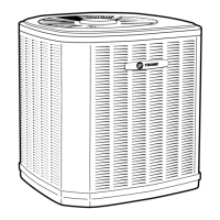
18-AC95D1-1 13
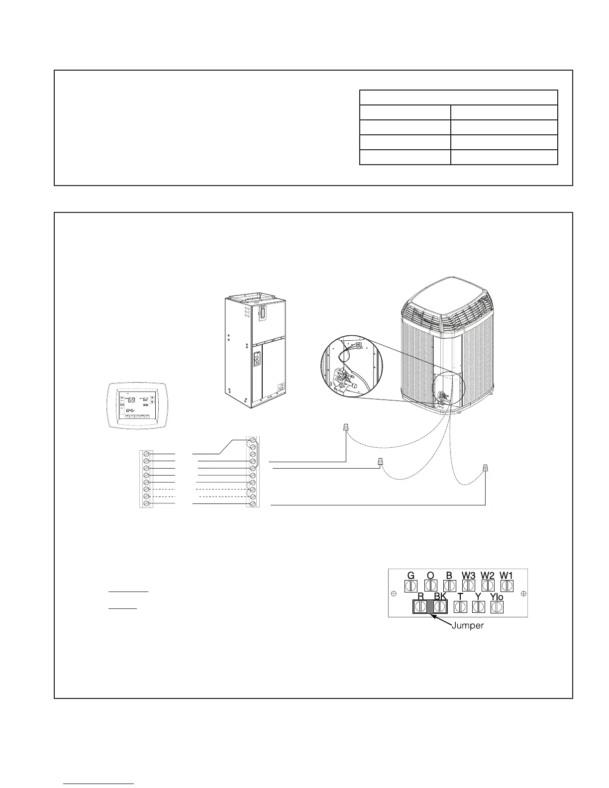
11.2 Low Voltage Hook-up Diagrams
Red
Yellow
Brown
Green
White
Black
Purple
Blue
W1
B
W3
W2
G
Y2
Y1
Yellow
Yellow/Black
Brown
Yellow/Red
Blue
Blue
R
Comfort Control
Variable Speed
Air Handler
W1
W2
W3
G
Y
B
O
BK
Y
LO
R
Neatly bundle all low voltage
wires behind the service
valve cover as shown.
Notes:
1. If electric heat does not have 3rd contactor (CH), connect a jumper wire
from W3 to W2. If electric heat does not have 2nd contactor (BH), connect a
jumper wire from W2 to W1.
2. Installer must remove the factory installed jumper between R and BK on the
air handler terminal strip.
3. Installer must add a field installed jumper between R and O on the air han-
dler terminal strip.
4. 4TTX8 units require 80% airflow with Y1 (low stage) and 100% airflow with
Y2 (high stage).
A) Connect Y1 from comfort control to Y at the VS air handler and to Y1
(yellow/black) at the AC.
B) Connect Y2 from comfort control to BK at the VS air handler and to Y2
(yellow/red) at the AC.
5. Comfort control may not have W2 or W3 terminals.
Section 11. Electrical - Low Voltage
11.1 Low Voltage Maximum Wire Length
Table 11.1 defines the maximum total length of
low voltage wiring from the outdoor unit, to the
indoor unit, and to the thermostat.
Table 11.1
24 VOLTS
WIRE SIZE MAX. WIRE LENGTH
18 AWG 150 Ft.
16 AWG 225 Ft.
14 AWG 300 Ft.
4TEE3F31-66
Variable Speed Air Handler Hook-up
Diagram

 Loading...