18-BC77D1-6 3
60’
Max
Vertical
Change
Standard
Line Set
60’ Max
Line Length
60’
Max
Vertical
Change
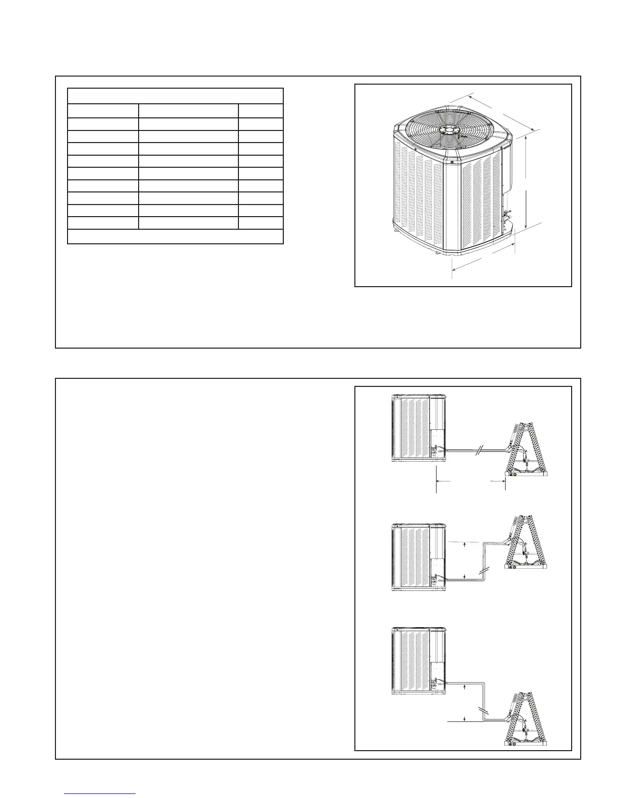
Unit Dimensions and Weight
Models H x D x W (in)
Weight* (lb)
4TWB4018G
29 x 30 x 33 204
4TWB4024E
33 x 34 x 37 255
4TWB4030E
41 x 34 x 37 281
4TWB4036G
33 x 34 x 37 261
4TWB4042E
41 x 34 x 37 313
4TWB4048E
45 x 34 x 37 331
4TWB4049E
45 x 34 x 37 331
4TWB4060E
45 x 34 x 37 332
4TWB4061E
45 x 34 x 37 332
* Weight values are estimated.
Section 2. Unit Location Considerations
2.1 Unit Dimensions and Weight
2.2 Refrigerant Piping Limits
1. The maximum length of refrigerant lines
from outdoor to indoor unit should NOT
exceed sixty (60) feet.
2. The maximum vertical change should not
exceed sixty (60) feet*.
3. Service valve connection diameters are
shown in Table 5.1.
Note: For line lengths greater than sixty (60)
feet, Refer to Refrigerant Piping Application
Guide, SS-APG006-EN or Refrigerant Piping
Software Program, 32-3312-03 (or latest revi-
sion).
* 061 Heat Pump is restricted to maximum
vertical change of 30 ft.
Table 2.1
*
*
When mounting the outdoor unit on a roof, be
sure the roof will support the unit’s weight.
Properly selected isolation is recommended to
alleviate sound or vibration transmission to the
building structure.
Please refer to application bulletin SSC-
APG001-EN for detailed mounting information.
 Loading...