20
18-BB34D1-19B-EN
EECCMM FFaann MMoottoorr AAddjjuussttmmeennttss
If the airflow needs to be increased or decreased, see
the Airflow Table in the Service Facts. Information on
changing the speed of the blower motor is in the
Blower Performance Table.
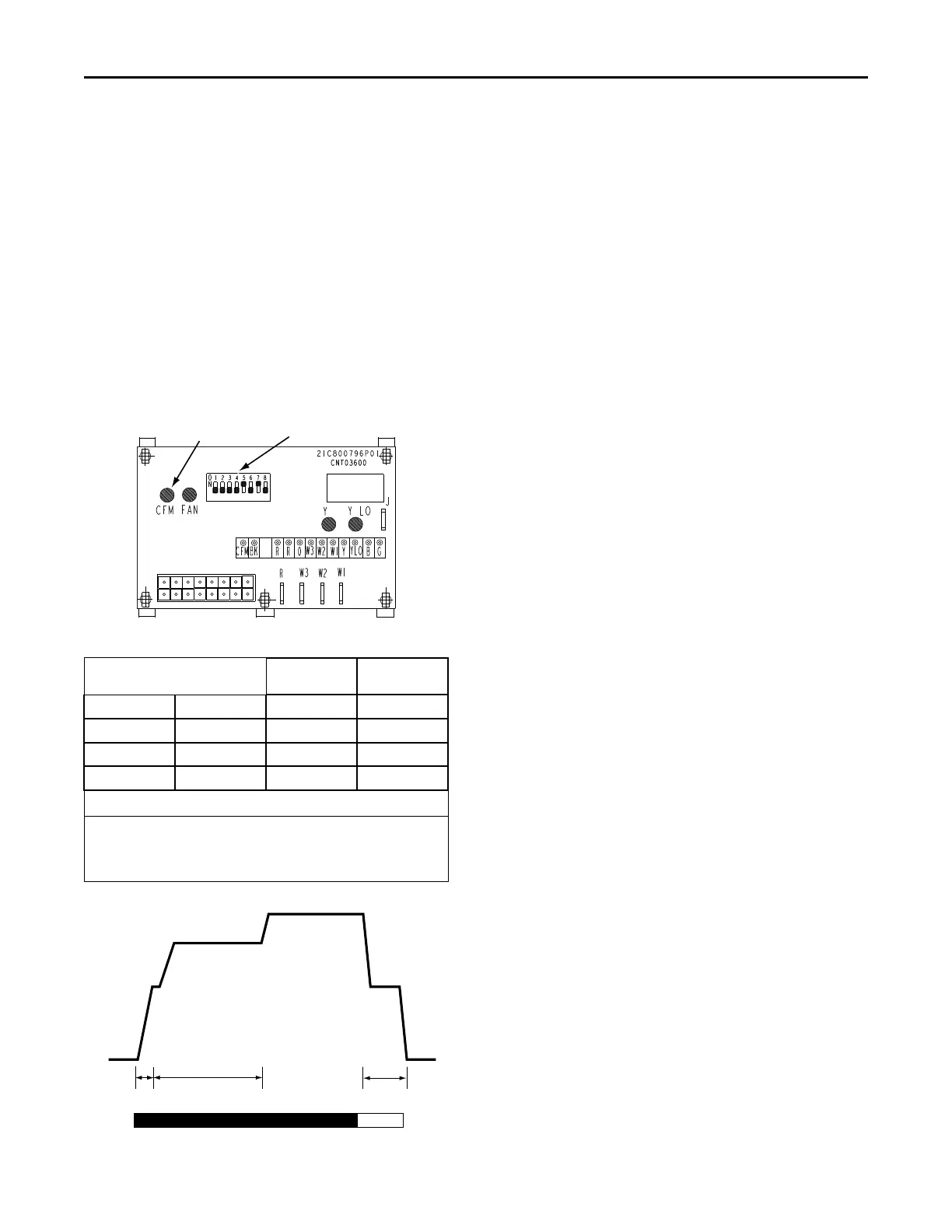
Blower speed changes are made on the ICM Fan
Control mounted in the control box. The ICM Fan
Control controls the variable speed motor.
There is a bank of 8 dip switches located at the upper
left side of the board. The dip switches work in pairs to
match the cooling/heat airflow (CFM/TON), Fan off-
delay options, and electric heat airflow adjustment. The
switches appear as shown in Figure 8, p. 20.
Figure 8. ECM Fan Control
CFM
SELECTION
LIGHT
DIP
SWITCHES
Table 11. Cooling Off - Delay Options
SWITCH SETTNGS SELECTION NOMINAL
AIRFLOW
5 - OFF 6 - OFF NONE SAME
5 - ON 6 - OFF 45 SECONDS 100%*
5 - OFF 6 - ON 1.5 MINUTES 50%
5 - ON 6 - ON ** 50 -100%
* - This setting is equivalent to the BAY24X045 relay benefit.
** - This ENHANCED MODE selection provides a ramping up and
ramping down of the blower speed to provide improved comfort,
quietness, and potential energy savings. The graph below show
the ramping process.
OFF OFF
50%
80%
100% if necessary
50%
Dehumidify
Fast Coil Cooling
and Heating
Efficiency
7.5
minutes
3
minutes
1
minute
FAN OPERATION (CFM)
COMPRESSOR OPERATION ON
OFF
as required
Final Installation Checklist
IImmppoorrttaanntt:: Perform a final unit inspection to be sure
that factory tubing has not shifted during
shipment. Adjust tubing if necessary so
tubes do not rub against each other when
the unit runs. Also be sure that wiring
connections are tight and properly secured.
☐ Does the unit run and operate as described in the
Sequence of Operation section in response to the
room thermostat?
☐ Are the condenser fan and indoor blower operating
correctly with proper rotation and without undue
noise?
☐ Is the compressor operating correctly and has the
system been checked with a charging chart?
☐ Has the voltage and running current been checked
to determine if it is within limits?
☐ Has the thermostat been checked for calibration
and the air discharge grills adjusted to balance the
system?
☐ Has the ductwork been checked for air leaks and
condensation?
☐ Has the furnace manifold pressure been checked
and adjusted if necessary?
☐ Has the heating air temperature rise been checked?
☐ Has the unit been checked for tubing and sheet
metal rattles? Are there any other unusual noises to
be checked?
☐ Are all covers and panels in place and properly
fastened?
☐ Has the owner been instructed on the proper
operation and maintenance of the unit? Be sure to
leave this manual with the owner.
Maintenance
Owner Maintenance
Some of the periodic maintenance functions of the unit
can be performed by the owner; this includes replacing
the disposable or cleaning the permanent air filters,
cleaning the unit cabinet, cleaning the condenser coil,
and conducting a general unit inspection on a regular
basis.
FFiilltteerrss
When the system is in constant operation, inspect the
filters at least once each month.
If the unit has disposable-type filters, replace them with
new filters of the same type and size. DDoo nnoott aatttteemmpptt
ttoo cclleeaann ddiissppoossaabbllee ffiilltteerrss..
Permanent-type filters can be cleaned by washing them
with a mild detergent and water. Make sure that the
filters are thoroughly dry before reinstalling them in
the unit (or duct system).
UUnniitt SSttaarrttuupp
 Loading...