18-EB31D1-1F-EN
23
Electrical Wiring
WWAARRNNIINNGG
IINNSSTTAALLLLAATTIIOONN WWAARRNNIINNGG —— HHIIGGHH
VVOOLLTTAAGGEE MMOOVVIINNGG PPAARRTTSS!!
FFaaiilluurree ttoo ffoollllooww tthhiiss WWaarrnniinngg ccoouulldd rreessuulltt iinn
pprrooppeerrttyy ddaammaaggee,, sseevveerree ppeerrssoonnaall iinnjjuurryy,, oorr
ddeeaatthh..
BBooddiillyy iinnjjuurryy ccaann rreessuulltt ffrroomm hhiigghh vvoollttaaggee
eelleeccttrriiccaall ccoommppoonneennttss,, ffaasstt mmoovviinngg ffaannss,, aanndd
ccoommbbuussttiibbllee ggaass.. FFoorr pprrootteeccttiioonn ffrroomm tthheessee
iinnhheerreenntt hhaazzaarrddss dduurriinngg iinnssttaallllaattiioonn aanndd sseerrvviicciinngg,,
tthhee mmaaiinn ggaass vvaallvvee mmuusstt bbee ttuurrnneedd ooffff aanndd tthhee
eelleeccttrriiccaall ssuuppppllyy mmuusstt bbee ddiissccoonnnneecctteedd.. IIff
ooppeerraattiinngg cchheecckkss mmuusstt bbee ppeerrffoorrmmeedd wwiitthh tthhee uunniitt
ooppeerraattiinngg,, iitt iiss tthhee tteecchhnniicciiaann’’ss rreessppoonnssiibbiilliittyy ttoo
rreeccooggnniizzee tthheessee hhaazzaarrddss aanndd pprroocceeeedd ssaaffeellyy..
NNoottee:: This unit is factory wired for 230V. See wiring
diagram for 208V conversion.
EElleeccttrriiccaall CCoonnnneeccttiioonnss
Electrical wiring and grounding must be installed in
accordance with local codes or, in the absence of local
codes, with the National Electrical Code ANSI/NFPA 70,
Latest Revision.
DDiissccoonnnneecctt SSwwiittcchh
Provide an approved weatherproof disconnect within
close proximity and wwiitthhiinn ssiigghhtt ooff tthhee uunniitt..If
disconnect must be mounted to the cabinet, the
location shown in Figure 15, p. 24 should be the only
one considered.
OOvveerr CCuurrrreenntt PPrrootteeccttiioonn
The branch circuit feeding the unit must be protected
as shown on the unit's rating plate.
PPoowweerr WWiirriinngg
The power supply lines must be run in weather-tight
conduit to the disconnect and into the side of the unit
control box. Provide strain relief for all conduit with
suitable connectors.
Provide flexible conduit supports whenever vibration
transmission may cause a noise problem within the
building structure.
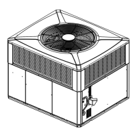
1. Remove the Control/Heat access panel. Pass the
power wires through the Power Entry hole in the
end of the unit. Figure 13, p. 23
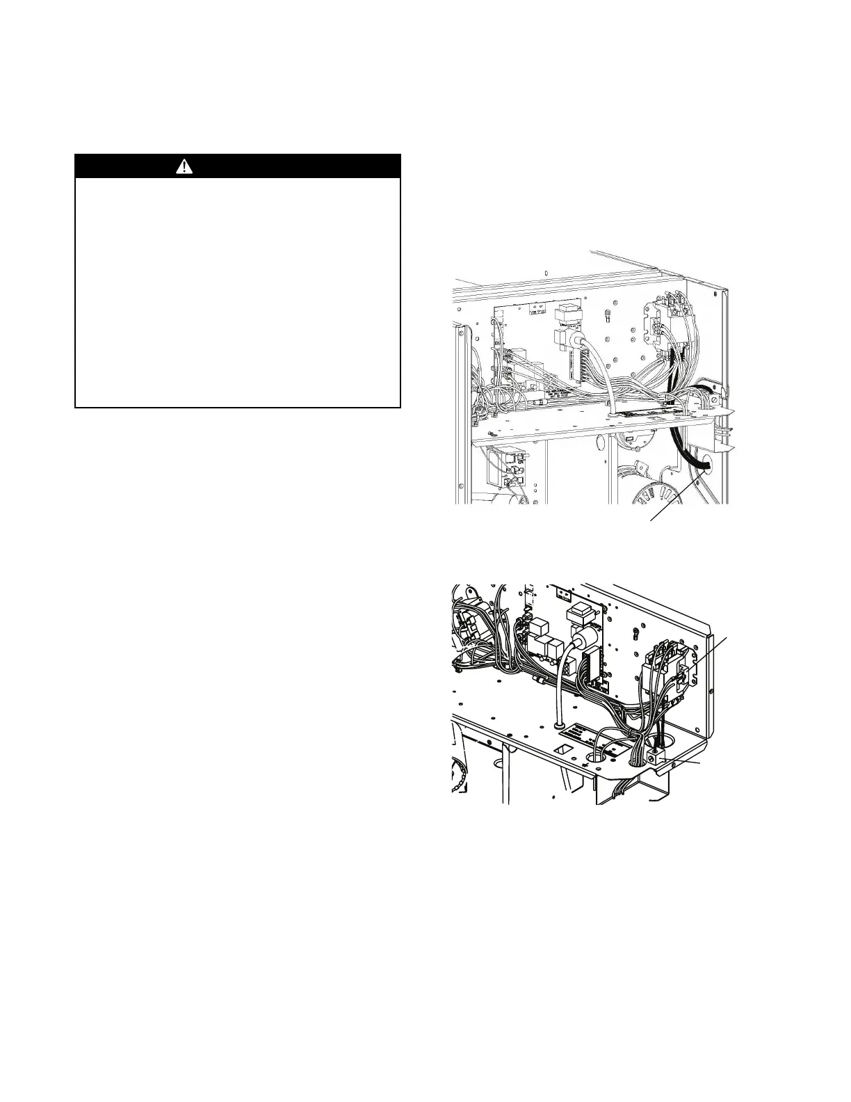
2. Connect the high voltage wires to the appropriate
contactor terminals. Single phase units use a two
(2) pole contactor and three phase units use three
(3) pole contactor. Connect the ground to the
ground lug on the chassis. See Figure 14, p. 23.
Be sure all connections are tight.
GGRROOUUNNDDIINNGG:: TTHHEE UUNNIITT MMUUSSTT BBEE EELLEECCTTRRIICCAALLLLYY
GGRROOUUNNDDEEDD IINN AACCCCOORRDDAANNCCEE WWIITTHH LLOOCCAALL CCOODDEESS
OORR TTHHEE NNAATTIIOONNAALL EELLEECCTTRRIICC CCOODDEE..
NNoottee:: Unit must be grounded for ignitor to operate
properly. Gas pipe to unit is not an adequate
ground. Ground the unit internally as provided.
See wiring diagram for location in .
Figure 13. Power Wiring
Run power supply lines through weather-tight
conduit and secure to unit with strain relief.
Figure 14. Power Connections
 Loading...