Page 20
Installer’s Guide
Thermostat Heat Anticipator
Set the heat anticipator of the thermostat to equal the amperage
draw of the gas valve
IMPORTANT: Upon completion of wiring, check all electrical con-
nections, including factory wiring within the unit.
Make sure all connections are tight. Replace and secure all electri-
cal box covers and access panels before leaving the unit or turning
on the power to the unit.
Step 5—Unit Startup
Pre-Start Quick Checklist
● Is the unit properly located and level with the proper clearance?
See Figure 4.
● Is the duct work correctly sized, run, taped, insulated, and
weatherproofed with proper unit arrangement? See Ductwork
Installation section.
● Is the gas piping correctly sized, run, trapped, and purged of air?
See Gas Piping section.
● Is the condensate line properly sized, run, trapped, and pitched?
● Is the filter of the correct size and number? Is it clean and in
place?
● Is the wiring properly sized and run according to the unit wiring
diagram?
● Are all the wiring connections, including those in the unit, tight?
● Has the unit been properly grounded and fused with the recom-
mended fuse size? See Wiring Data.
● Is the thermostat level, correctly wired, well located, and set for
the proper heat anticipation?
● Have the air conditioning systems been checked at the service
ports for charge and leak tested if necessary?
● Does the condenser fan and indoor blower turn free without rub-
bing, and are they tight on the shafts?
● Has the indoor blower speed been determined and the proper
speed been set? See the Unit Wiring Diagram.
● Has all work been done in accordance with applicable local and
national codes?
● Are all covers and access panels in place to prevent air loss and
safety hazards?
Control Wiring (Class II)
Low voltage control wiring should not be run in conduit with power
wiring unless Class 1 wire of proper voltage rating is used. Route
the thermostat cable or equivalent single leads of No. 18 AWG
colored wire from the thermostat subbase terminals through the
rubber grommet on the unit. See Figures 2 or 5 for the control
entry (24V Entry) location. Make connections as shown on the
unit wiring diagram.
Do not short thermostat wires since this will damage the control
transformer.
Refer to Table 6 for recommended wire sizes and lengths for install-
ing the unit thermostat. The total resistance of these low voltage
wires must not exceed one (1) ohm. Any resistance in excess of 1
ohm may cause the control to malfunction because of the exces-
sive voltage drop.
Table 6. Thermostat Wire Size and Maximum Length
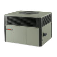
Contactor
Unit Ground Lug
Figure 20. Power Connections
eziSerihWtgneLmumixaM
8517
65121
40102
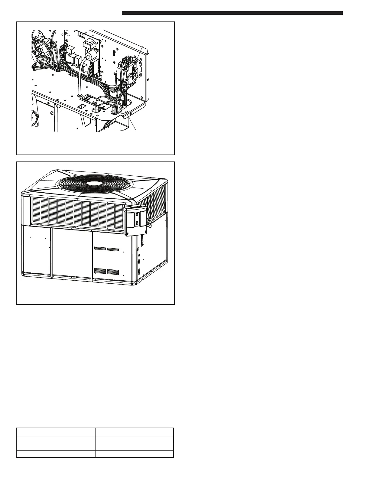
Figure 21. Mounted Disconnect Location
 Loading...