6 88-A4AC5001-1A-EN
Section 4. Setting the Unit
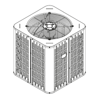
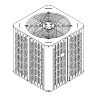
4.1 Pad Installation
When installing the unit on a support pad, such
as a concrete slab, consider the following:
• The pad should be at least 1” larger than the
unit on all sides.
• The pad must be separate from any structure.
• The pad must be level.
• The pad should be high enough above grade
to allow for drainage.
• The pad location must comply with National,
State, and Local codes.
Section 5. Refrigerant Line Considerations
5.1 Refrigerant Line and Service Valve Connection Sizes
Table 5.1
Line Sizes Service Valve Connection Sizes
Model
Vapor
Line
Liquid
Line
Vapor Line
Connection
Liquid Line
Connection
A4AC5018D
3/4 3/8 3/4 3/8
A4AC5024D
3/4 3/8 3/4 3/8
A4AC5030D
3/4 3/8 3/4 3/8
A4AC5036D
7/8 3/8 3/4 3/8
A4AC5042D
7/8 3/8 7/8 3/8
A4AC5048D
7/8 3/8 7/8 3/8
A4AC5060D
1-1/8 3/8 7/8 3/8
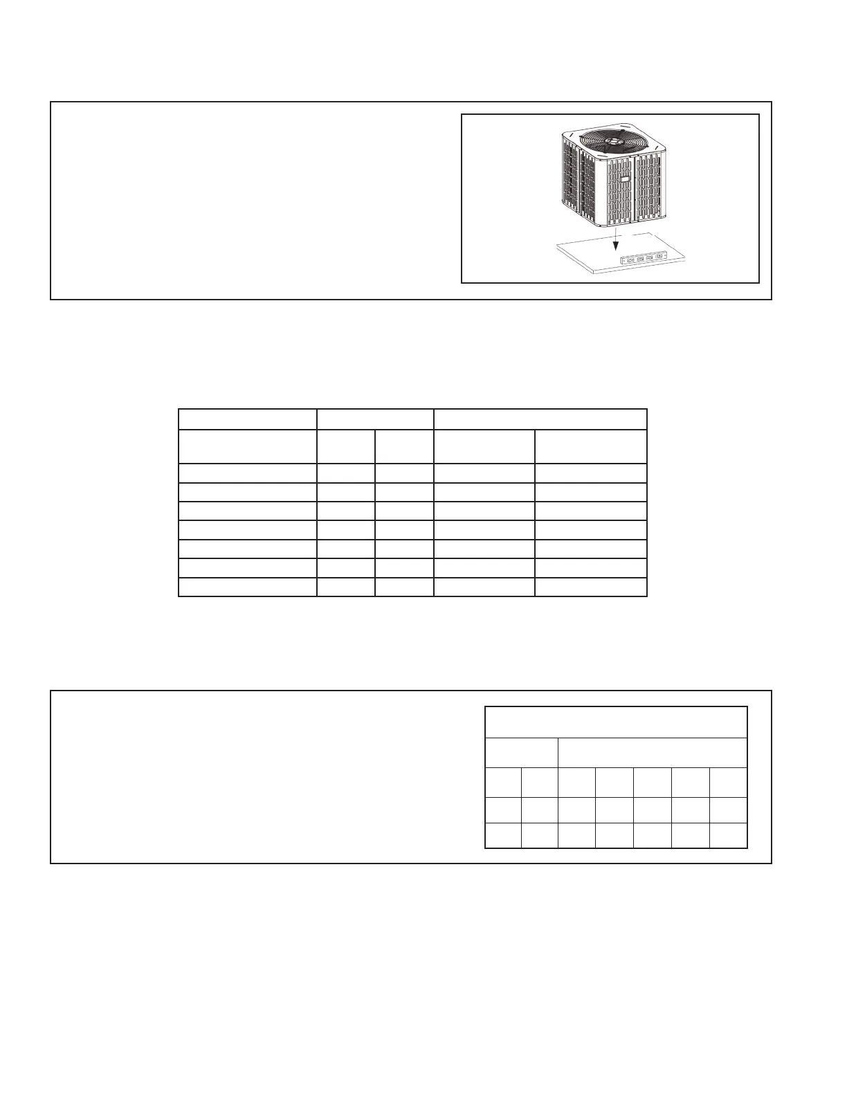
5.2 Factory Charge
The outdoor condensing units are factory
charged with the system charge required for the
outdoor condensing unit, ten (10) feet of tested
connecting line, and the smallest rated indoor
evaporative coil match. Always verify proper
system charge via subcooling (TXV/EEV) or
superheat (fixed orifice) per the unit nameplate.
TUBING INFORMATION
LINE TYPE
REFRIGERANT TO ADD AT SPECIFIED
ADDITIONAL LENGTH
Suction
Line
Liquid
Line
20 ft 30 ft 40 ft 50 ft 60 ft
3/4” 3/8" 3 oz 9 oz 15 oz 21 oz 27 oz
7/8" 3/8" 3 oz 9 oz 16 oz 22 oz 28 oz
 Loading...