A801X-SVX001-1B-EN
23
Gas Flow in Cubic Feet Per Hour
2 Cubic Foot Dial
Sec. Flow Sec. Flow Sec. Flow Sec. Flow
10 732 31 236 52 141 86 85
11 666 32 229 53 138 88 83
12 610 33 222 54 136 90 81
13 563 34 215 55 133 94 78
14 523 35 209 56 131 98 75
15 488 36 203 57 128 100 73
16 458 37 198 58 126 104 70
17 431 38 193 59 124 108 68
18 407 39 188 60 122 112 65
19 385 40 183 62 118 116 63
20 366 41 179 64 114 120 61
21 349 42 174 66 111 130 56
22 333 43 170 68 108 140 52
23 318 44 166 70 105 150 49
24 305 45 163 72 102 160 46
25 293 46 159 74 99 170 43
26 282 47 156 76 96 180 41
27 271 48 153 78 94 190 39
28 262 49 149 80 92 200 37
29 253 50 146 82 89
30 244 51 144 84 87
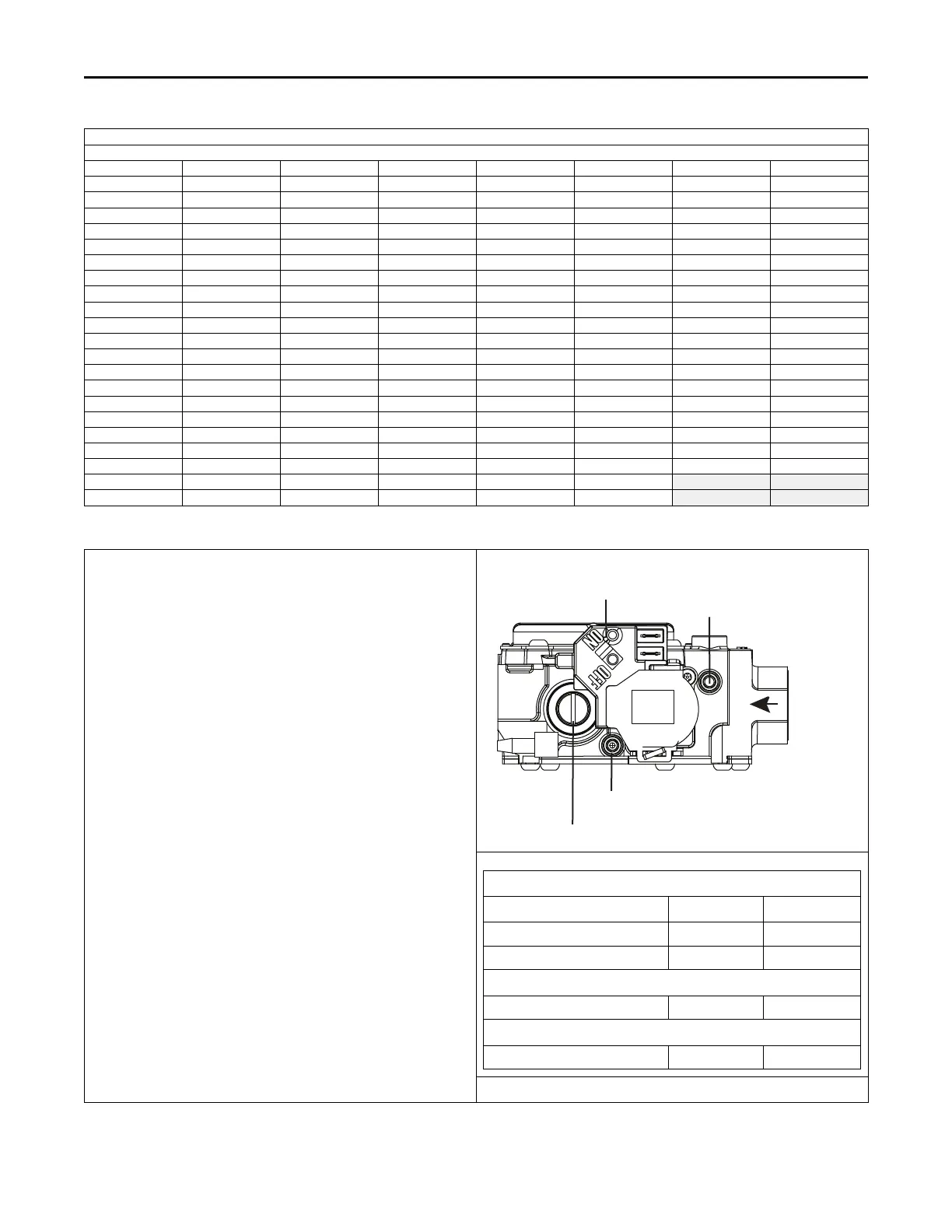
Gas Valve Adjustment
Changes can be made by adjusting the manifold pressure, or changing
orifices (orifice change may not always be required). To adjust the
manifold pressure:
1. Turn off all electrical power to the system.
2. Loosen (Do Not remove) the pressure tap test set screw one turn
with 3/32" hex wrench.
a. The pressure tap adjustment kit (KIT07611) contains a 3/32"
hex wrench, a 5/16" hose and a connector and can be
ordered through Global Parts.
3. Attach a manifold pressure gauge with flexible tubing to the outlet
pressure boss marked "OUT P" on White- Rodgers gas valve
model 36J.
4. Turn on system power and make a call for heating.
5. Adjust gas heat by removing the low (LO) adjustment regulator
cover screw.
a. To increase outlet pressure, turn the regulator adjust screw
clockwise.
b. To decrease outlet pressure, turn the regulator adjust screw
counterclockwise.
c. Adjust regulator until pressure shown on manometer
matches the pressure specified in the table.
The input of no more than nameplate rating and no less than
93% of the nameplate rating, unless the unit is derated for
high altitude.
d. Replace and tighten the regulator cover screw securely.
6. Cycle the valve several times to verify regulator setting.
a. Repeat steps 5-6 if needed.
7. Turn off all electrical power to the system.
8. Remove the manometer and flexible tubing and tighten the
pressure tap screw.
9. Using a leak detection solution or soap suds, check for leaks at the
pressure outlet boss and pressure tap test screw.
10. Turn on system power and check operation of the unit.
Outlet Pressure Boss
1st Stage (LO) Manifold Pressure Adjustment
Inlet Pressure
Boss
Gas Valve On/Off
Toggle Switch
White-Rodgers 36J
Maximum and Minimum INLET Pressure (inches w.c.)
Natural Gas Propane
Maximum 13.8 13.8
Minimum 5 11
Fuel Manifold Pressure Settings (inches w.c.)
All models 3.5 10
Orifice sizes for Natural Gas and Propane
All models 45 56
FFuurrnnaaccee GGeenneerraall IInnssttaallllaattiioonn
 Loading...