18-CD19D8-18 29
Installer’s Guide
TWIN
TWIN
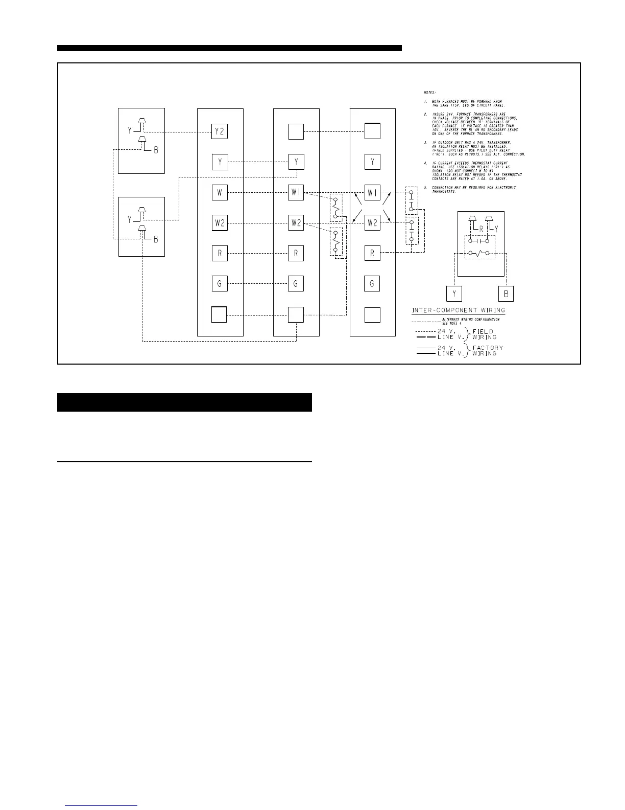
TWINNING CONNECTION DIAGRAM
FOR TWINNING UX/DX-R FURNACES
2 STAGE HEAT / 2 STAGE COOLING THERMOSTAT
2 STAGE HEATING
1 STAGE COOLING
THERMOSTAT FURNACE NO. 1
FURNACE NO. 2
BLOWER OPERATION OF
UNIT NO. 2 IS SYNCRONIZED
WITH UNIT NO. 1 VIA SIGNALS
FROM TWIN CONNECTION.
SEE NOTE 4
OUTDOOR UNIT NO. 1
(NO TRANSFORMER)
OUTDOOR UNIT NO. 2
(NO TRANSFORMER)
SEE NOTE 3
R2
R2
SEE NOTE 5
ISOLATION RELAY
(FIELD SUPPLIED)
SEE NOTE 4
ISOLATION RELAY
SEE NOTE 4
R1
R1
OUTDOOR UNIT
(WITH TRANSFORMER)
SEE NOTE 3
RC
ISOLATION RELAY
(FIELD SUPPLIED)
ALTERNATE CONNECTION
B/C
B/CB/C
From Dwg. 21B341338 Rev. 2
WARNING
!
CARBON MONOXIDE POISONING HAZARD
Failure to follow the installation instructions for the venting
system being placed into operation could result in carbon
monoxide poisoning or death.
ELECTRICAL CONNECTIONS
Make wiring connections to the unit as indicated on enclosed
wiring diagram. As with all gas appliances using electrical
power, this furnace shall be connected into a permanently
live electric circuit. It is recommended that furnace be
provided with a separate “circuit protection device” electric
circuit. The furnace must be electrically grounded in accor-
dance with local codes or in the absence of local codes with
the National Electrical Code, ANSI/NFPA 70 or CSA C22.1
Electrical Code, if an external electrical source is utilized.
The integrated furnace control is polarity sensitive.
The hot leg of the 120V power supply must be connected to
the black power lead as indicated on the wiring diagram.
Provision for hooking up an electronic air cleaner and or
humidifier is provided on the integrated control.
Refer to the SERVICE FACTS literature and unit wiring
diagram attached to furnace.
 Loading...