EasyManuals Logo
Home>Trane>Chiller>CCUF-R454B

Trane CCUF-R454B User Manual

Trane CCUF-R454B
53 pages
To Next Page IconTo Next Page
To Previous Page IconTo Previous Page
Page #33 background imageLoading...
Page #33 background image
Page 33
9 CONNECTION TO THE REMOTE CONDENSER
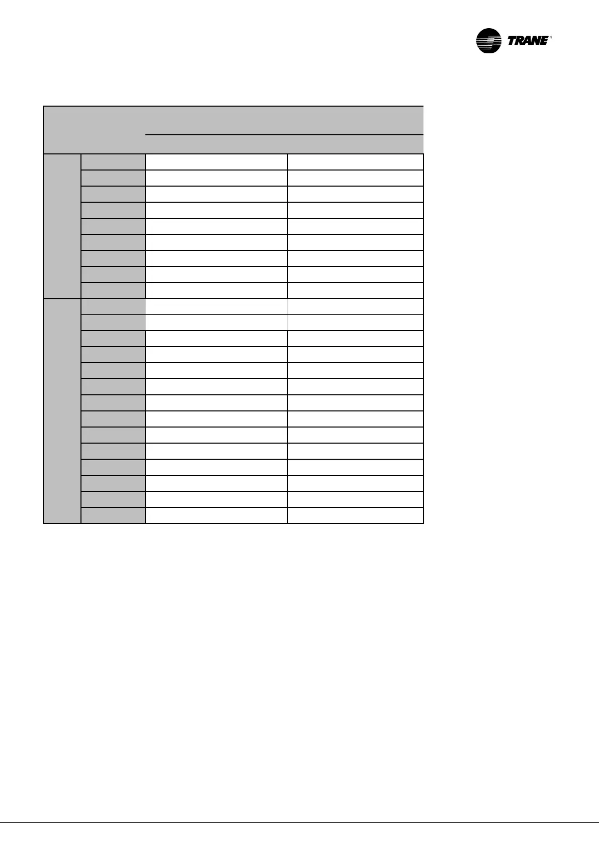
CCUF
CONNECTION LINES RECOMMENDED
DIAMETERS
Discharge line Ø [mm] Liquid line Ø [mm]
One refrigerant circuit
sizes
013
28
16
015
28
16
019
28
16
023
28
16
025
28
16
029
35
28
033
35
28
037
35
28
041
35
28
Two refrigerant circuits sizes
042
28
22
048
28
22
056
35
28
064
35
28
072
35
28
078
35
28
088
42
28
096
42
28
112
42
28
128
42
28
144
42
35
162
42
35
176
42
35
192
42
35
IMPORTANT:
The party in charge of the supply of the condenser and of its refrigerant piping is responsible of implementing all the required
protections to comply with the PED requirements for the design pressure of the condenser installed.
IMPORTANT:
The only electrical signals that the Trane CCUF unit provides to the remote condenser are:
- Enabling signal
- 0-10 V modulating signal

Questions and Answers:

Question and Answer IconNeed help?

Do you have a question about the Trane CCUF-R454B and is the answer not in the manual?

Trane CCUF-R454B Specifications

General IconGeneral
BrandTrane
ModelCCUF-R454B
CategoryChiller
LanguageEnglish

Related product manuals