10 18-CD20D1-18
Installer’s Guide
Blower Door Hinge and Bottom Filter Rack Installation
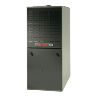
Airflow
e
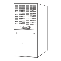
Filter Rack Assembly
r
Airflow
TABLE 4
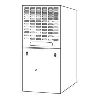
VIEW
ENGAGEMENT
HOLE DETAIL
(Typical both sides
and blower deck)
Blower Deck
Engagement
Hole
Filter
Rack
Furnace
Cabinet
Side
Filter Rack
Retaining
Screw/Pin
Engagement Hole
For
Bottom Return
Filter Rack
Installation With
t
y
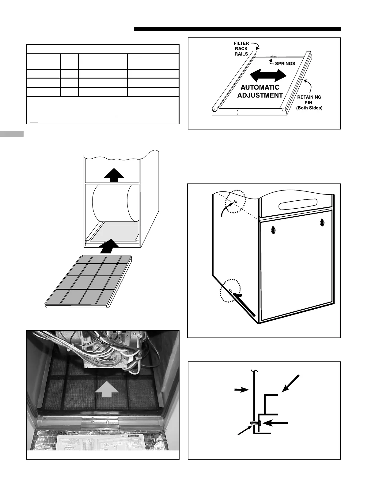
BOTTOM FILTER RACK INSTALLATION
With the filter removed, the filter rack is compressed and
then inserted into the bottom of the furnace. The retaining
screw/pin on each side inserts into engagement holes at the
bottom of the furnace cabinet side.
UPFLOW FURNACE RETURN AIR FILTERS
CABINET
WIDTH
QTY*
CABINET
BOTTOM FILTER
CABINET
SIDE FILTER
17-1/2" 1 17" X 25" X 1" 17-1/2" X 25" X 1"
21" 1 20" X 25" X 1" 17-1/2" X 25" X 1"
24-1/2" 1 24" X 25" X 1" 17-1/2" X 25" X 1"
*NOTE - On 5 ton airflow models, if the airflow
requirement exceeds 1800 CFM, these models will
require filters on both sides; OR
1 side and the bottom;
OR
just the bottom.
 Loading...