81
Unit Start-Up (Continued)
To relocate the fresh air/return air connecting rod to bal-
ance the fresh air damper pressure drop against the return
static pressure, use the following steps. If no adjustment is
necessary, proceed to step 17.
12.Remove the drive rod and swivel from the crank arm(s).
If only one hole requires changing, loosen only that
end.
13.Manually open the return air dampers to the full open
position.
14.Manually close the fresh air dampers.
15.Reattach the drive rod and swivel to the appropriate
hole(s). The length of the drive rod may need to be ad-
justed to align with the new hole(s) location. If so,
loosen the lock nut on the drive rod against the swivel.
Turn the swivel "in" or "out" to shorten or lengthen the
rod as necessary. For some holes, both ends of the rod
may need to be adjusted.
16.Tighten the lock nut against the swivel(s).
17.Plug the holes after the proper CFM has been estab-
lished.
Table 4-5
F/A Damper Travel Adjustment
Position of Damper
Connecting Rod Crank Arm Hole
(See Figure 4-5) Configuration
Position #1 2 - 3 Use the tables below to select the appropriate
Position #2 2 - 4 crank arm hole configuration based on the;
Position #3 2 - 5 a. specific unit,
Position #4 2 - 6 b. operating CFM,
Position #5 1 - 8 c. and return static pressure.
Position #6 1 - 7
Note:
As shi
ed from the factor
, the connect rod is
installed in Position #1.
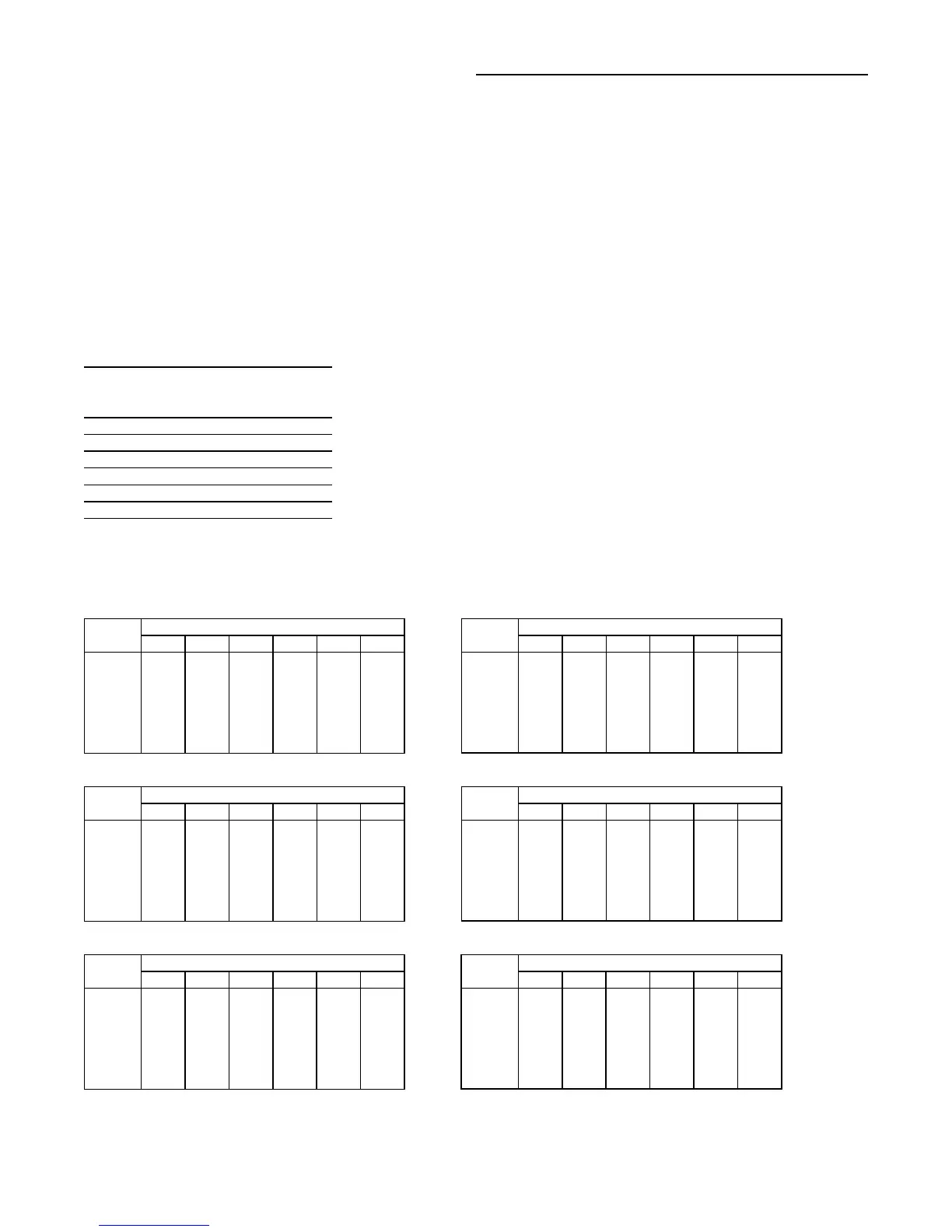
Fresh Air Damper Pressure Drop (inches w.c. )
20 and 25 Ton Units 50 - 55 Ton Units
Damper Position Damper Position
CFM #1 #2 #3 #4 #5 #6 CFM #1 #2 #3 #4 #5 #6
4000 0.03 0.04 0.06 0.13 0.16 0.33 10000 0.03 0.04 0.09 0.18 0.23 0.55
6000 0.03 0.04 0.10 0.20 0.30 0.90 14000 0.09 0.12 0.20 0.35 0.50 1.36
8000 0.19 0.21 0.32 0.52 0.75 1.75 18000 0.31 0.36 0.50 0.79 1.10 -
9000 0.30 0.35 0.48 0.76 1.08 2.40 20000 0.45 0.51 0.70 1.05 1.57 -
10000 0.45 0.51 0.70 1.05 1.57 - 22000 0.58 0.66 0.75 1.30 1.95 -
11000 0.62 0.71 0.95 1.42 2.15 - 24000 0.75 0.88 1.10 1.75 2.50 -
30 Ton Units 60 - 75 Ton Units
Damper Position Damper Position
CFM #1 #2 #3 #4 #5 #6 CFM #1 #2 #3 #4 #5 #6
6000 0.03 0.04 0.07 0.15 0.20 0.43 14000 0.03 0.04 0.12 0.25 0.35 1.05
8000 0.03 0.05 0.11 0.21 0.30 0.90 18000 0.19 0.21 0.32 0.52 0.75 1.75
10000 0.15 0.19 0.26 0.43 0.62 1.50 22000 0.45 0.51 0.70 1.05 1.57 -
11000 0.20 0.25 0.37 0.60 0.85 1.85 26000 0.70 0.80 1.02 1.58 2.30 -
12000 0.31 0.36 0.50 0.79 1.10 2.40 28000 0.88 1.03 1.30 2.20 - -
13000 0.42 0.48 0.62 0.97 1.42 - 30000 1.05 1.22 1.55 2.65 - -
40 Ton Units 90 - 130 Ton Units
Damper Position Damper Position
CFM #1 #2 #3 #4 #5 #6 CFM #1 #2 #3 #4 #5 #6
8000 0.03 0.04 0.08 0.16 0.21 0.52 27000 0.31 0.36 0.50 0.79 1.10 2.40
10000 0.03 0.05 0.11 0.21 0.30 0.90 32000 0.55 0.64 0.72 1.25 1.88 -
12000 0.10 0.13 0.21 0.38 0.55 1.40 36000 0.75 0.88 1.10 1.75 2.50 -
14000 0.20 0.25 0.37 0.60 0.85 1.85 40000 1.00 1.18 1.50 2.50 - -
16000 0.41 0.46 0.60 0.94 1.38 - 43000 1.20 1.42 1.92 - - -
18000 0.56 0.65 0.74 1.28 1.92 - 46000 1.40 1.58 2.29 - - -

 Loading...


