52
PKGP-SVX010B-EN
Notes:
• Single zone VAV is designed to be used with a
zone sensor. If a unit is configured for Single
zone VAV operation but is connected to a
thermostat, the control will revert to multi-speed
(2-speed) indoor fan control and staged
compressor control. This drastically reduces
the energy savings available with this design.
• eFlex™ is designed to be used with a zone
sensor. If a unit is configured for variable speed
compressor operation but is connected to a
thermostat, the control will revert to multi-speed
indoor fan control and staged compressor
control. This drastically reduces the energy
savings available with this design.
Air Filters
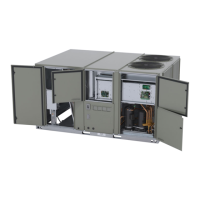
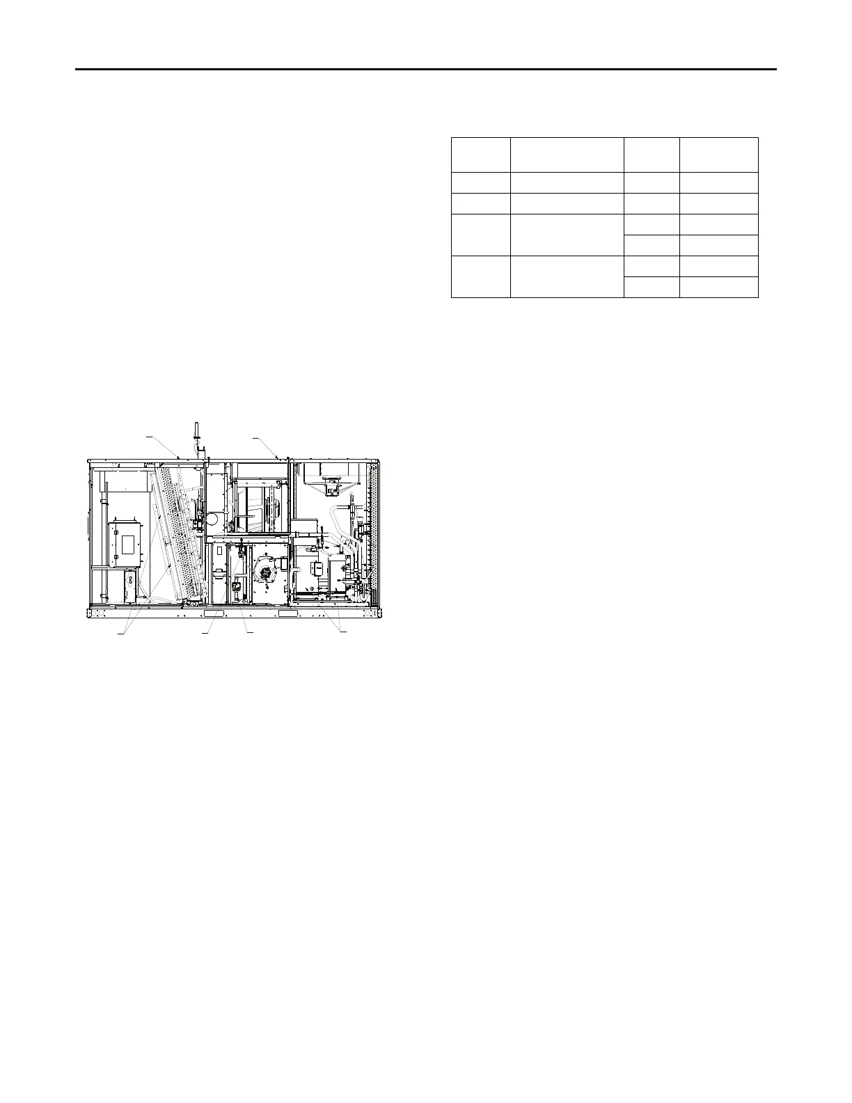
Figure 40. Gas unit overview
RETURN AIR
SUPPLY AIR
AIR FILTERS
PRESSURE SWITCH
GAS VALVE
COMPRESSORS
Filters are to be used with this unit. Units ship from the
factory with filters installed.
It is very important to keep the central duct system air filters
clean. Be sure to inspect them at least once each month
when the system is in constant operation. (In new homes,
check the filters every week for the first 4 weeks.) See the
following table for the required filter size(s).
If you have disposable type filters, replace them with new
filters of the same type and size. Do not attempt to clean
disposable filters.
Permanent type filters can be cleaned by washing them
with a mild detergent and water. Ensure that the filters are
thoroughly dry before reinstalling them in the unit (or duct
system).
It may be necessary to replace permanent filters annually if
washing fails to clean the filter, be sure to use the same
type and size as was originally installed.
Table 16. Recommended standard filters
Tons
Unit Model
Number
Qty
Filter Size
(L x W x D)
12.5
DSJ150A**(0,A)(L,M,H)
8 20 x 24x 2
15
DSJ180A**(0,A)(L,M,H)
8 20 x 24x 2
20
DSJ240A**(0,A)(L,M,H)
4 20 x 24x 2
4 20 x 30 x 2
25
DSJ300A**(0,A)(L,M,H)
4 20 x 24x 2
4 20 x 30 x 2
Heating System
Heating Cycle Operation
The unit heating system is a solid-state electronic ignition
control that lights the furnace burners each time the
thermostat calls for heat. At the end of each heating cycle
the furnace burners are extinguished. This type of system
is called Direct Spark Ignition (DSI).
A normal heating cycle begins when the air temperature
drops below the thermostat setting. The thermostat then
energizes the heating electrical circuit that starts and
controls the furnace burners. Shortly after the burners
ignite the indoor fan starts and circulates warm air through
the conditioned space.
When the air temperature rises to the thermostat setting
the thermostat deenergizes the heating electrical circuit,
which in turn extinguishes the burners. The indoor fan
continues to circulate warm air until most of the heat is
removed from the unit's combustion chamber.
Safety Controls
• The unit is equipped with an automatic reset safety limit
control to prevent overheating. When the control
opens, it shuts down the heating electrical circuit until
the unit cools down sufficiently. Inadequate airflow (i.e.,
caused by dirty filters or defective fan motor) may
cause the unit to cycle on and off as the limit trips and
automatically resets. If you suspect the unit is cycling
on its limit control, immediately contact a service
person for instructions
• If flames from the burner are not properly drawn into
the heat exchanger, a flame rollout protection control
will open causing the furnace to shut off. The cause
must be investigated by a qualified service person.
• If installed, the condensate overflow switch will shut
down the unit before a drain pan overflow occurs.
Heating System Start-Up
Because your unit has an automatic ignition system, it is
easy to start the heating cycle at the beginning of the
heating season. In order for the unit to operate properly
and safely, the furnace needs air for both combustion and
ventilation. Check to make sure that all air openings are
Gas Heat Operation and Maintenance
 Loading...