73
RTAA-IOM-3
2. Isolated 2-10 VDC Voltage Source
Input
Set DIP Switch SW1-1 of Options
Module 1U2 to “OFF”. Connect the
voltage source to terminals TB1 -4 (+)
and TB1 -5 (-) on Options Module
1U2. CWS is now based on the
following equation:
CW Setpoint 0 F = (VDC x 8.125) -
16.25
Sample values for CWS vs. VDC
signals are shown in Table 13.
Minimum setpoint
= 0 F (2.0 VDC input)
Maximum setpoint
= 65 F (9.4 VDC input)
Maximum continuous input voltage
= 15 VDC
Input impedance = 40.1 Kohms
SW1 -1 off)
3. Isolated 4-20 mA Current Source
Input
Set DIP Switch SW1-1 of Options
Module 1U2 to “ON”. Connect the
current source to terminals TB1-4
(+)and TB1-5 (-). CWS is now based
on the following equation:
Setpoint °F = (mA x 4.0625) - 16.25
Sample values for CWS vs. mA
signals are shown in Table 13.
Minimum setpoint = 0 F (4.0 mA)
Maximum setpoint = 65 F (18.8 mA)
Maximum continuous = 30 mA
input current
Input impedance = 499 ohms
SW1 -1 on)
Note: The negative terminal TB1 -5 is
referenced to the UCM chassis ground.
To assure correct operation, 2-10 VDC
or 4-20 mA signals must be isolated or
“floating” with respect to the UCM
chassis ground. See Figures 34 thru 36.
External Current Limit Setpoint
(CLS): Remote Resistor/
Potentiometer, Voltage Source 2-10
VDC or Current Source 4-20 mA
This option allows the external setting
of the Current Limit Setpoint,
independent of the Front Panel Current
Limit Setpoint, by one of three means:
1. A remote resistor/potentiometer
input (fixed or adjustable)
2. An isolated voltage input 2-10 VDC
3. An isolated current loop input 4-20
mA
Methods 2 and 3 are usually used in
interfacing with a Generic BAS.
To enable external Current Limit
Setpoint operation, Item 31 of Menu 3,
“External Current Limit Setpoint WE”,
should be set to “E” using the Front
Panel Operator Interface.
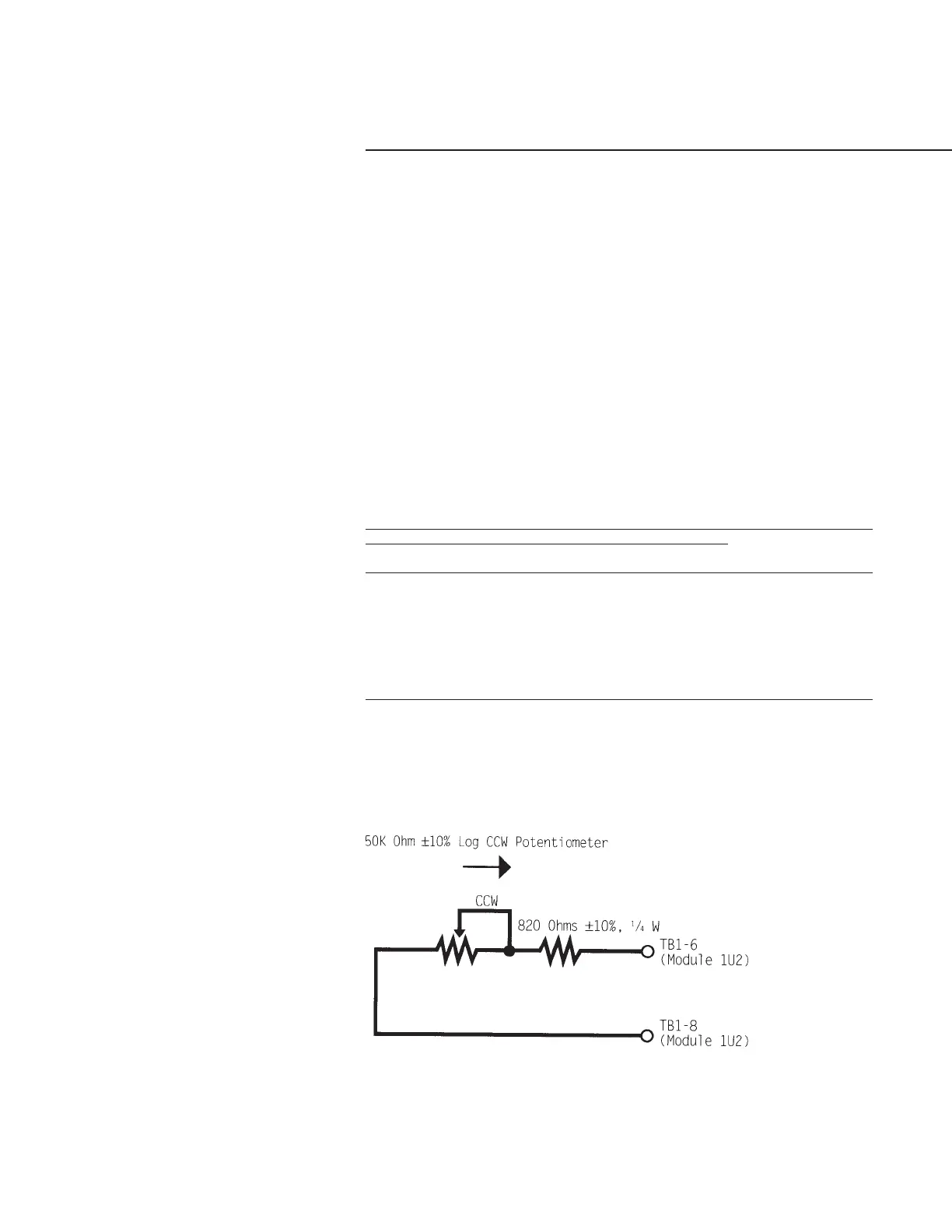
1. Remote Resistor/Potentiometer Input
To cover the entire range of Current
Limit Setpoints; (40 to 120%), a field
furnished 50 Kohm log taper
potentiometer (±10%) and a fixed
820 ohm (±1 0%) 1/4 Waft resistor
should be wired in series and
connected to terminals TB1 -6 and
TB1 -8, of options module 1U2, as
shown in Figure 39.
Table 14
Input Values Vs. External Current Limit Setpoint
Inputs
Resulting Current
Resistance (Ohms) Current (mA) Voltage (Vdc) Limit Setpoint (% RLA)
49000 4.0 2.0 40
29000 6.0 3.0 50
19000 8.0 4.0 60
13000 10.0 5.0 70
9000 12.0 6.0 80
6143 14.0 7.0 90
4010 16.0 8.0 100
2333 18.0 9.0 110
1000 20.0 10.0 120
Figure 39
Resistor and Potentiometer
Arrangement for External
Current Limit Setpoint
 Loading...


