81
RTAA-IOM-3
Figure 41
(Continued from Previous Page)
1 Schrader valve
2 Suction temperature sensor*
3 Manufacturing process tube
4 Suction service valve (optional)
5 Motor winding thermostat*
6 Discharge temperature sensor
7 Pressure relief valve (450 psi)
8 High pressure cutout (405 psi)*
9 Discharge check valve
10 Evaporator waterside vent
11 Discharge line shutoff valve
12 Oil separator in/out cap
13 Saturated condensing temperature
sensor*
14 Condenser header
15 Subcooler header
16 Liquid line shutoff valve
17 25 micron filter/drier
18 Liquid line sight glass
19 Electronic expansion valve*
20 Saturated evaporator temperature
sensor*
21 Evaporator waterside drain
22 Leaving water temperature sensor*
23 Leaving water connection
24 Entering water connection
25 Entering water temperature sensor*
26 Drain with Schrader valve
27 Oil line
28 Entering oil, cooler header
29 Leaving oil cooler header
30 Schrader valve with stem depressor
31 Oil line shutoff valve
32 5 micron oil filter
33 Master solenoid valve*
34 Oil line to load/unload slide valve
solenoids
35 Injection oil check valve
36 Heater
37 Slide valve solenoids and orifices*
38 Oil flow differential pressure switch*
39 Compressor Drain Plug
40 Domestic water heater (optional)
41 Oil line thermostat (option,
Domestic Water Heater)
42 Oil line bypass solenoid valve
(option, Domestic Water Heater)
*UCM Input/Output Control
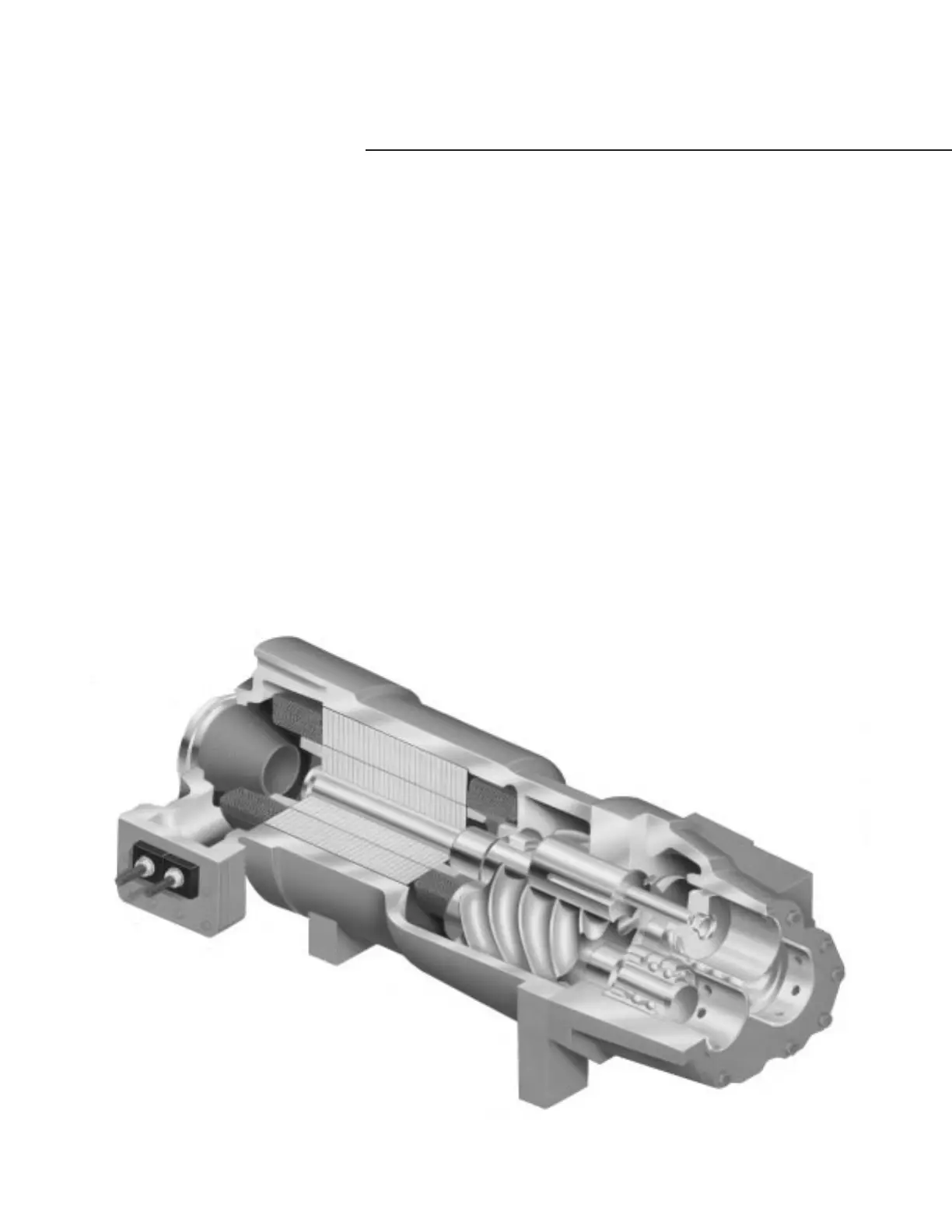
Figure 42
Typical RTAA Compressor
REFRIGERATION SYSTEM AND CONTROL COMPONENTS

 Loading...

