70
RTAA-IOM-3
Alarm/Running/Maximum
Capacity Outputs
Terminals 1 to 8 on terminal strip TB4
of the 1U1 board provide a variety of
contact outputs. These are dependent
upon the setting of Menu Item 4E and
its relationship to diagnostics,
compressors operating and the system
operating at full capacity.
Table 11
Alarm/Running/Maximum
Capacity Relay Output
Configurations
Relay Output Configuration
1: RLY 1 = Alarm
RLY 2 = Compressor Running
RLY 3 = Maximum Capacity
2: RLY 1 = Circuit I Alarm
RLY 2 = Circuit 2 Alarm
RLY 3 = Maximum Capacity
3: RLY 1 = Alarm
RLY 2 = Circuit 1 Running
RLY 3 = Circuit 2 Running
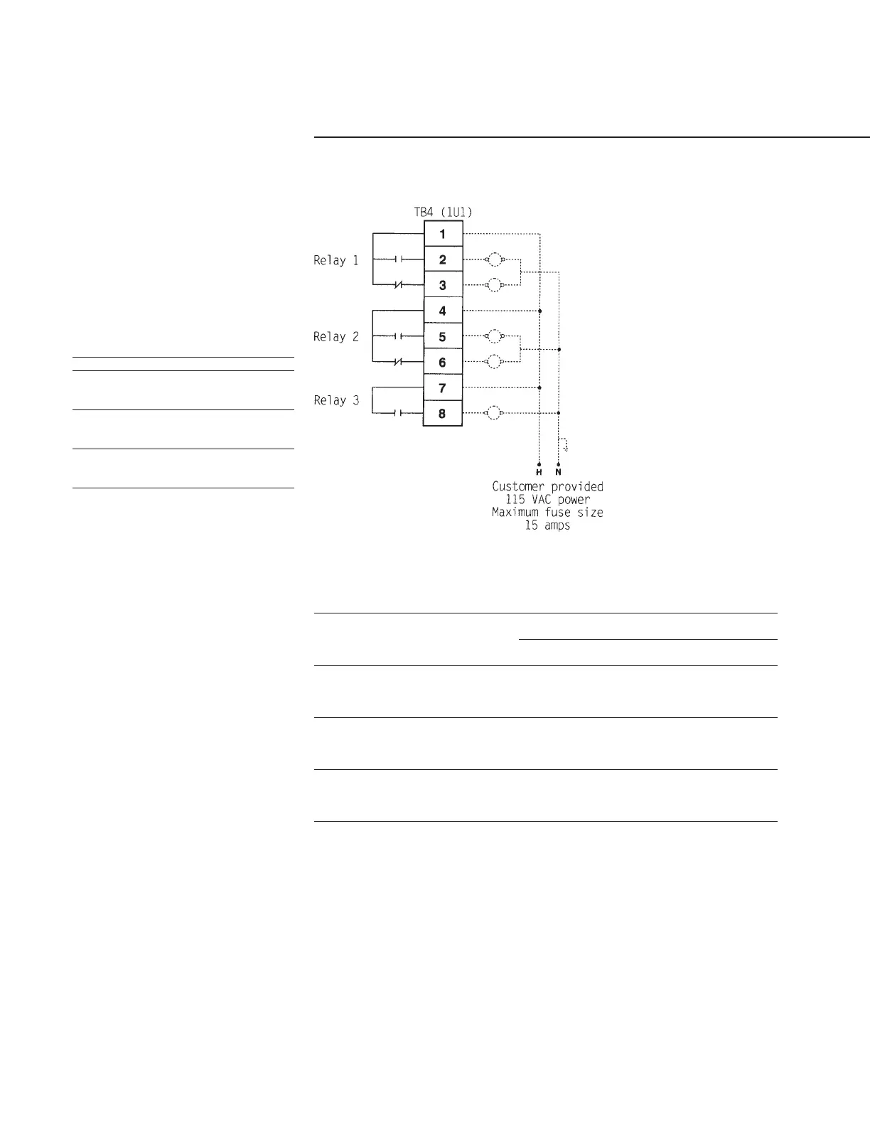
As shown in Figure 37, there are three
relays. Relays 1 and 2 have SPDT
contacts. Relay 3 has SPST normally
open contacts. The relays can provide
three different output configurations, as
shown in Table 11, and each
configuration offers four choices as to
how the alarm relay is to respond to a
set of diagnostics.
Table 12 shows the twelve settings
available in Menu Item 4E and the
diagnostics which are issued for each
set of conditions.
Figure 37
Alarm/Running/Maximum
Capacity Contact Outputs
Table 12
Alarm/Running/Maximum Capacity Menu Settings
Diagnostics that the
Relays Output Alarm Relay(s) is Active
Menu Item 4E Configuration MMR/ MAR/
Setting (Table 11) CMR diag. CAR diag. IFW diag.
1 1 YES NO NO
2 1 YES YES NO
3 1 YES YES YES
4 1 YES NO YES
5 2 YES NO NO
6 2 YES YES NO
7 2 YES YES YES
8 2 YES NO YES
9 3 YES NO NO
10 3 YES YES NO
11 3 YES YES YES
12 3 YES NO YES
Notes:
MMR = Machine Manual Reset
CMR = Circuit Manual Reset
MAR = Machine Auto Reset
CAR = Circuit Auto Reset
IFW = Informational Warnings
 Loading...

