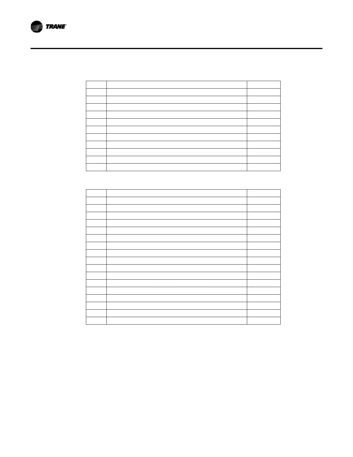
Table 4. Menu P3
30 External Chilled Water Setpoint d/E
31 External Current Limit Setpoint d/E
32 Ice Machine Control d/E
33 Active Ice Termination Setpoint Not a setting
34 Front Panel Ice Termination Setpoint
35 Return Reset d/E
36 Zone Reset d/E
37 Outdoor Reset d/E
38 Reset Ratio Setpoint
39 Start Reset Setpoint
3A Maximum Reset Setpoint
3b External Circuit Lockout d/E
Table 5. Menu P4
40 Leaving Water Temperature Cutout Setpoint
41 Low Refrigerant Temperature Cutout Setpoint
42 Condenser Limit Setpoint
43 Balanced Compressor Starts and Hours (Lead/Lag) d/E
44 SI Display Units d/E
45 Unit Line Voltage
46 Under/Over Voltage Protection d/E
47 Phase Imbalance Protection d/E
48 Phase Reversal Protection d/E
49 Superheat Setpoint
4A(1) EXV Control Response Setpoint – Circuit 1
4A(2) EXV Control Response Setpoint – Circuit 2
4b Leaving Water Temperature Control Response Setpoint
4C ICS Address
4d(1) Fan Control Deadband Bias – Circuit 1
4d(2) Fan Control Deadband Bias – Circuit 2
4E Programmable Relay Setup
4F Restart Inhibit Timer
Replacement Procedure
6 PART-SVN251A-EN
 Loading...


