Replacement Procedure
PART-SVN251A-EN 5
v. Press the Set Point Down button once.
vi. Press the Set Point
Up button twice.
vii.You should now be at menu P4. Press
the Set Point Up button once to get to menu P5.
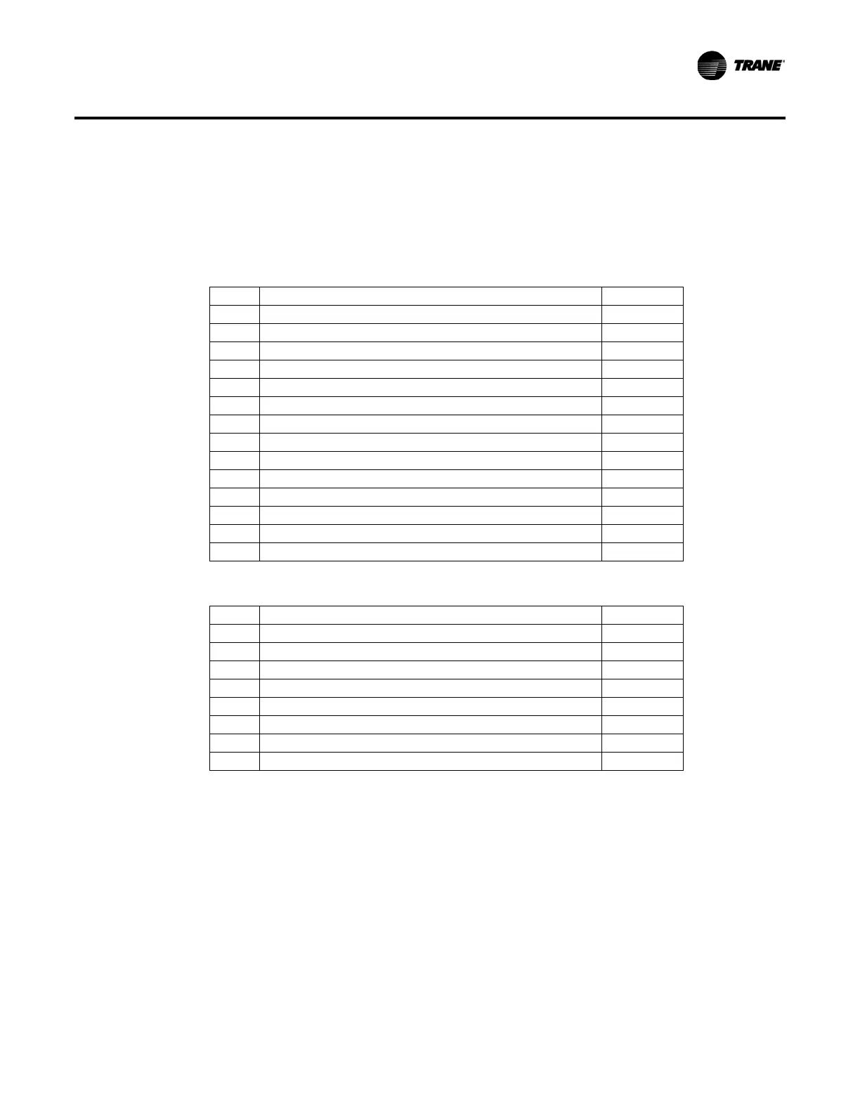
Unit Configuration Settings
Table 2. Menu P1
10 Front Panel Chilled Water Setpoint
11 Design Delta Temperature Setpoint
12 Differential to Start Setpoint
13 Front Panel Current Limit Setpoint
14 Outdoor Air Temperature (optional) Not a Setting
15 Low Ambient Lockout d/E
16 Low Ambient Lockout Setpoint
17 Condenser Entering Water Temperature (Not applicable for RTAA)
18 Condenser Leaving Water Temperature (Not applicable for RTAA)
19(1) Service Pumpdown Circuit 1 d/E
19(2) Service Pumpdown Circuit 2 d/E
1A(1) Circuit Lockout – Circuit 1 d/E
1A(2) Circuit Lockout – Circuit 2 d/E
1b(1) Diagnostics Reset – Circuit 1 d/E
1b(2) Diagnostics Reset – Circuit 2 d/E
Table 3. Menu P2
20–28 These menu items are not settings Not settings
29(A) Compressor A Starts
29(B) Compressor B Starts
29(C) Compressor C Starts
29(D) Compressor D Starts
2A(A) Compressor A Hours
2A(B) Compressor B Hours
2A(C) Compressor C Hours
2A(D) Compressor D Hours
 Loading...


