52 RTAD-SVX01F-E4
Installation - Electrical
Alarm and Status Relay Output
(Programmable Relays)
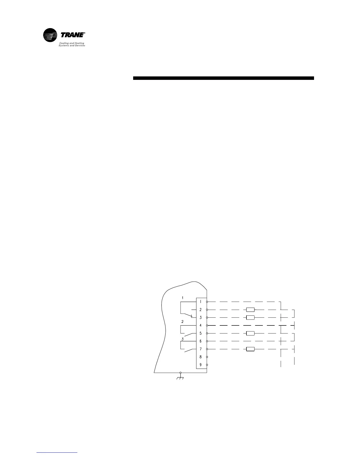
Alarm/Running/Maximum Capacity
Outputs Terminals 1 to 7 on terminal
strip TB4 of the A1 board provide a
variety of contact outputs on the
RTAD. These are dependent on the
setting of Programmable Relay
Setup (Service Setting Menu) and its
relationship to diagnostics,
compressors operating, and the
system operating at full
capacity. As shown in Figure 26,
there are three relays.
Notes: For Free Cooling units a
programmable relay output
(terminals A70 J17-C12-NO12 and
-NC12) is available. It provides a
normally close contact. Following
functions are available:
❏ A70 ready to work, or working: the
normally open contact will close
as soon as the controller is
powered and run, without any
sensor(s) or sequence(s) failure.
❏ A70 failure: the normally open
contact will close as long as there
is a failure detect on sensor(s) or
in sequence(s).
❏ Free cooling on: the normally
open contact will close as long as
the unit is making cold water with
free cooling.
Figure 26 - Alarm / Running / Maximum capacity relay output for the RTAD unit.
 Loading...