18-CE04D1-1B-EN
21
Gas Valve Adjustment
Changes can be made by adjusting the manifold pressure, or changing
orifices (orifice change may not always be required). To adjust the
manifold pressure:
1. Turn off all electrical power to the system.
2. Attach a manifold pressure gauge with flexible tubing to the outlet
pressure boss marked "OUT P" on White- Rodgers gas valve
model 36J.
3. Loosen (Do Not remove) the pressure tap test set screw one turn
with 3/32" hex wrench.
a. The pressure tap adjustment kit (KIT07611) contains a 3/32"
hex wrench, a 5/16" hose and a connector and can be
ordered through Global Parts.
4. Turn on system power and make a call for 2nd stage heating.
Insure that the unit is in second stage heating by verifying 24 VAC
is measured between C and HI on the gas valve.
Important: Adjust 2nd stage on the gas valve before attempting to
adjust 1st stage.
5. Adjust 2nd stage gas heat by removing the high (HI) adjustment
regulator cover screw.
a. To increase outlet pressure, turn the regulator adjust screw
clockwise.
b. To decrease outlet pressure, turn the regulator adjust screw
counterclockwise.
c. Adjust regulator until pressure shown on manometer
matches the pressure specified in the table.
The input of no more than nameplate rating and no less than
93% of the nameplate rating, unless the unit is derated for
high altitude.
d. Replace and tighten the regulator cover screw securely.
e. Remove call for second stage heat, first stage heat is now
running.
6. Adjust 1st stage gas heat by removing the low (LO) adjustment
regulator cover screw.
a. To increase outlet pressure, turn the regulator adjust screw
clockwise.
b. To decrease outlet pressure, turn the regulator adjust screw
counterclockwise.
c. Adjust regulator until pressure shown on manometer
matches the pressure specified in the table.
The input of no more than nameplate rating and no less than
93% of the nameplate rating, unless the unit is derated for
high altitude.
d. Replace and tighten the regulator cover screw securely.
7. Cycle the valve several times to verify regulator setting.
a. Repeat steps 5-7 if needed.
8. Turn off all electrical power to the system.
9. Remove the manometer and flexible tubing and tighten the
pressure tap screw.
10. Using a leak detection solution or soap suds, check for leaks at the
pressure outlet boss and pressure tap test screw.
11. Turn on system power and check operation of the unit.
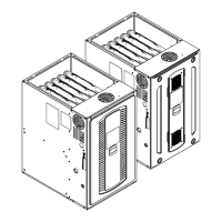
Outlet Pressure Boss
2nd Stage (HI) Manifold Pressure Adjustment
1st Stage (LO) Manifold Pressure Adjustment
Inlet Pressure
Boss
Gas Valve On/Off
Toggle Switch
White-Rodgers 36J
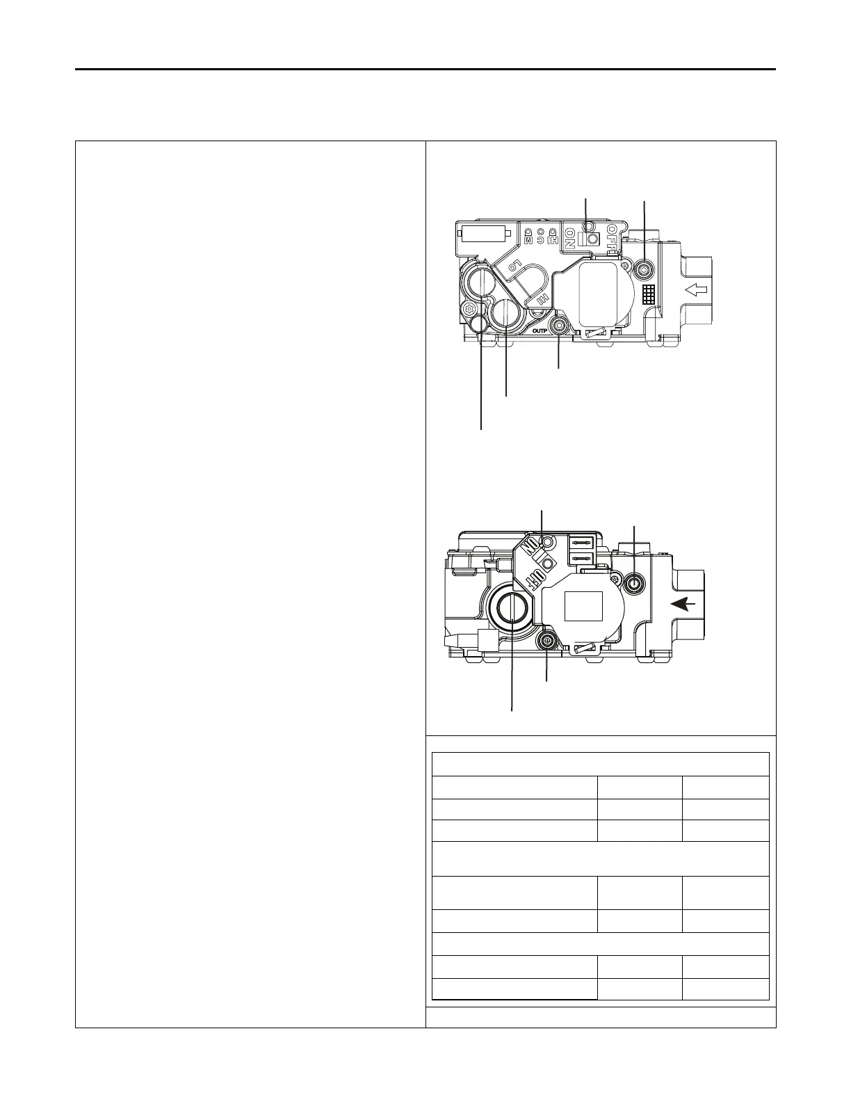
Outlet Pressure Boss
1st Stage (LO) Manifold Pressure Adjustment
Inlet Pressure
Boss
Gas Valve On/Off
Toggle Switch
White-Rodgers 36J
Maximum and Minimum INLET Pressure (inches w.c.)
Natural Gas Propane
Maximum 13.8 13.8
Minimum 5 11
Maximum and Minimum Fuel Manifold Pressure Settings (inches w.
c.) 2nd Stg/1st Stg
All models except S8X1D120,
S8X2D120
3.5/1.6 10/6
S8X1D120, S8X2D120 3.5/1.8 10/7.5
Orifice sizes for Natural Gas and Propane
All models except S8X1A026 45 56
S8X1A026 51 59
FFuurrnnaaccee GGeenneerraall IInnssttaallllaattiioonn
 Loading...