18-CE01D1-1M-EN
71
Upflow Furnace in Upflow Position — Left Side Vented Combustion Air
Changes need to be made to the inducer orientation when installing
the upflow furnace with the combustion air vented through the side.
Additional changes are needed for hose routing and PS2 rotation.
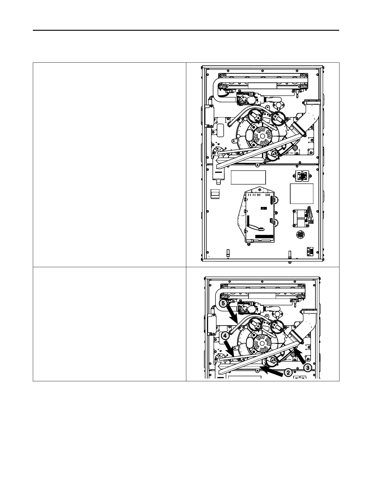
The figure to the right shows the furnace as it is sent from the factory.
Use the following steps to modify the furnace for upflow with side
venting of combustion air.
Important: Right side vent outlet is not allowed because condensate
will not drain.
Before proceeding, lay unit on its back to make conversion easier.
1. Disconnect all drain tubes from condensate trap.
Note: When removing condensate hoses from the condensate trap,
hold the trap with your hand to prevent the trap from breaking.
Removing the trap before the hoses is also an option.
2. Remove drain tubing from bottom of inducer housing.
3. Remove rain gutter tubing from inducer outlet.
4. Remove tubing from condensate pressure switch.
5. Remove tubing from PS2 to cold header.
FFuurrnnaaccee CCoommbbuussttiioonn AAiirr EExxhhaauusstt OOppttiioonnss
 Loading...


