34
18-CE18D1-1A-EN
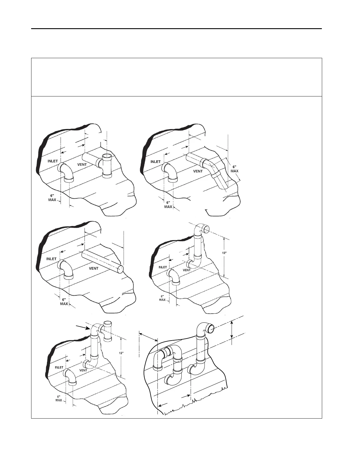
Table 2. Horizontal Venting Through Wall
The vent for this appliance shall not terminate
1. Over public walkways; or
2. Near soffit vents or crawl space vents or other areas where condensate or vapor could create a nuisance or hazard or cause property
damage; or
3. Where condensate vapor could cause damage or could be detrimental to the operation of regulators, relief valves. or other equipment.
Possible configurations for two pipe venting system. Both terminations must be located in the same pressure zone.
Important: Maintain 12” minimum clearance above highest anticipated snow level or grade, whichever is greater.
Note: All distances are centerline to centerline.
6” Min.
24” Max
.
12” Min.
15” Max
.
9” Minimum
minimum from end
of exhaust pipe to
end of inlet pipe
6” Min.
24” Max
.
12” Min.
15” Max
.
9” Minimum
minimum from end
of exhaust pipe to
end of inlet pipe
6” Min.
24” Max
.
12” Min.
15” Max
.
9” Minimum
minimum from end
of exhaust pipe to
end of inlet pipe
4” Min.
24” Max
.
Elbow and Tee
Must be as close
together as
possible
4” Min.
24” Max
.
12” Min. between
inlet and vent
terminations
VENT
INLET
6” Max.
to wall
FFuurrnnaaccee GGeenneerraall IInnssttaallllaattiioonn
 Loading...


