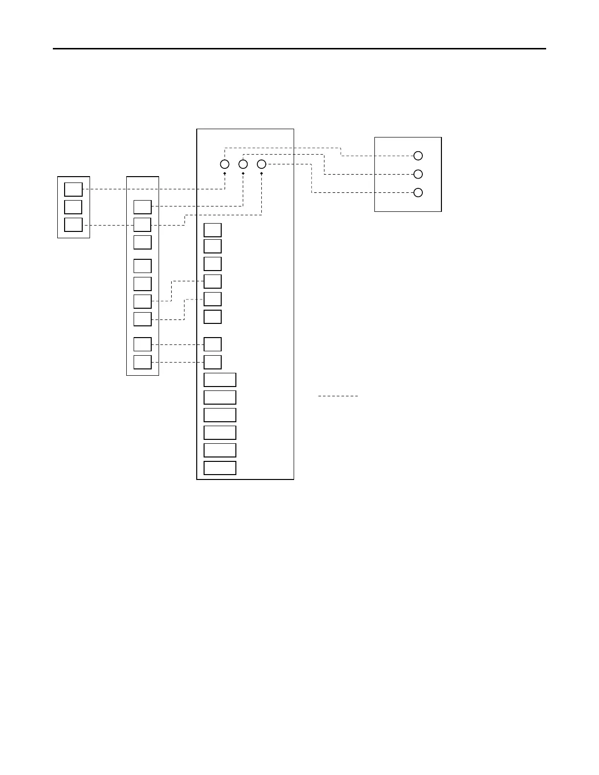
R
W2
G
W1
B/C
O
Y2
Y1
BK
W2
G
W1
O
Y2
Y1
BK
Indoor Unit
Relay Panel
Communicating
Control
HUM
HUM
AUX1
AUX1
AUX2
AUX2
W3
STG2
FAN
STG1
SOV
D
R
B
STG2
STG1
PWM
HUM
HUM
AUX1
AUX1
AUX2
AUX2
STG3
24V
ONLY
24V
ONLY
24V
ONLY
D
R
B
COMMUNICATING CONTROLS WITH NON-COMMUNICATING S9V2 FURNACE
AND COMMUNICATING VS COOLING/HP
D
R
B
Outdoor Unit
NOTES:
1. Cut the BK jumper at the indoor unit - After cutting the jumper, power must
be off or cycled on-off-on for the IFC to work properly
2. Requires an 850 control with software version 3.0+ or 1050. Not a valid
combination with 950 control
CPC=CFM/Ton cooling. Must be set to 400.
CPH=CFM/Ton heating. Must be set to 400.
Furnace LED’s will read “CoF“ continous fan during cooling and heat
pump operation.
24 V Field Wiring
 Loading...


