18-CE18D1-1A-EN
65
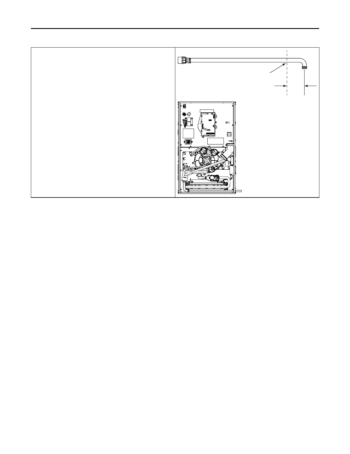
Attaching the condensate drain line.
1. Locate the condensate drain line assembly in the doc pack.
Important: It is best to cut the condensate drain hose assembly
longer than 4 inches and then fit in place. It can then be
trimmed to needed length. The 4 inch measurement is an
approximation.
2. Cut the condensate drain line assembly as shown.
3. Use a field supplied hose clamp to secure the condensate drain
line to the condensate trap.
4. Insert a field supplied piece of 1/2” CPVC pipe though the 11/16”
hole drilled through the cabinet and insert into drain line hose.
Secure with the spring clip.
Note: Seal around the condensate drain tubing where it exits the
cabinet.
11/16” DIAMETER HOLE MUST
BE CUT IN RIGHT SIDE OF CASE.
BOTTOM HOLE MUST BE PLUGGED.
CUT FACTORY SUPPLIED
CONDENSATE ASSEMBLY HOSE
AND ATTACH TO FIELD SUPPLIED
CPVC TUBE. SECURE WITH SPRING
CLIP AND
FIELD SUPPLIED HOSE
CLAMP.
DOWNFLOW FURNACES
RIGHT SIDE DRAIN
IF THE FURNACE IS
INSTALLED OVER A FINISHED
CEILING, OVERFLOW FROM
THE PRIMARY DRAIN VENT
STACK MUST FLOW INTO AN
AUXILIARY DRAIN PAN TO
PREVENT DAMAGE TO THE
FINISHED CEILING BELOW
CCoonnddeennssaattee DDrraaiinn IInnssttrruuccttiioonnss
 Loading...


