S9V2-VS-SVX001-1B-EN
81
27. Connect PS2 tubing to switch and new sensing
location.
IImmppoorrttaanntt:: Trim the condensate pressure switch
tubing to length to ensure there is no sag or
trap created.
28. Remove port cap on the right side of the inducer
and connect inducer condensate tubing. Connect
other end of inducer condensate tubing to top port
on the condensate trap. Cut tubing to length, if
necessary.
29. Install previously removed port cap onto bottom
port of the inducer.
30. Connect condensate pressure switch tubing to
pressure port on the condensate trap.
IImmppoorrttaanntt:: Cut to length to ensure there is no sag
or trap created.
31. Connect rain gutter condensate hose to the rain
gutter and the lower port of the condensate trap.
Upflow Furnace in Horizontal
Right Position - Left Side Vented
Combustion Air
Changes need to be made to the inducer orientation
when installing the upflow furnace in the horizontal
right position with the combustion air vented through
the bottom. Additional changes are needed for hose
routing, condensate trap location, and inducer port
caps, and the condensate plug.
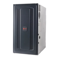
The figure below shows the furnace as it is sent from
the factory.
Use the following steps to modify the furnace for
horizontal right with bottom venting of combustion air.
Before proceeding, lay unit on its back to make the
conversion easier.
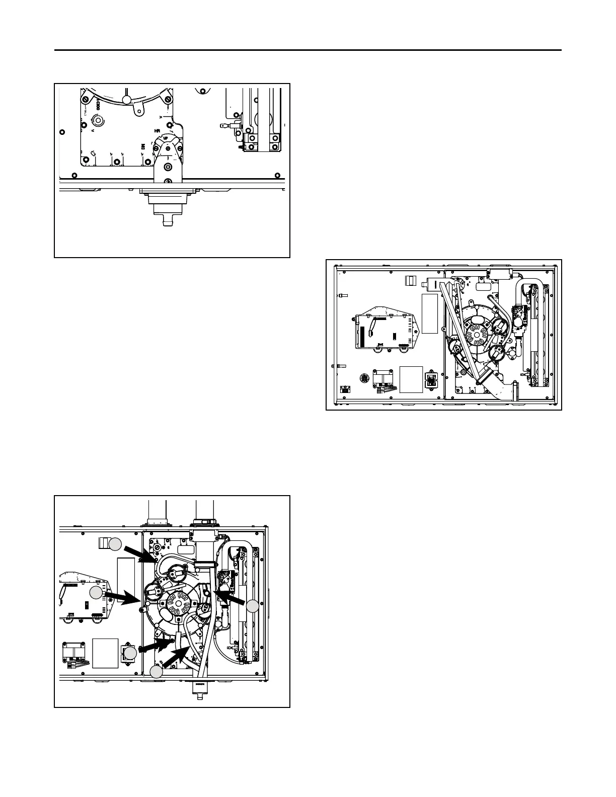
1. Remove all drain hoses from condensate trap.
NNoottee:: When removing condensate hoses from the
condensate trap, hold the trap with your hand to
prevent the trap from breaking. Removing the
trap before the hoses is also an option.
2. Remove tubing from PS2 pressure switch.
3. Remove drain tubing from bottom of inducer
housing.
4. Remove rain gutter tubing from inducer outlet.
5. Remove tubing from condensate pressure switch.
6. Remove the screws that hold the condensate trap
bracket. The condensate trap should not be
removed from the condensate trap bracket.
Remove assembly and retain for later installation.
7. Remove the condensate adapter located inside the
condensate trap connection on the cold header and
retain for later installation.
NNoottee:: The plastic condensate adapter with O-rings
located inside the cold header that is held in
place by the condensate trap bracket. Do not lose
this adapter. The condensate adapter needs to
be in place when the condensate trap bracket is
reattached.
FFuurrnnaaccee CCoommbbuussttiioonn AAiirr EExxhhaauusstt OOppttiioonnss
 Loading...