Mounting of Option Modules in Slot B
The power to the frequency converter must be disconnected.
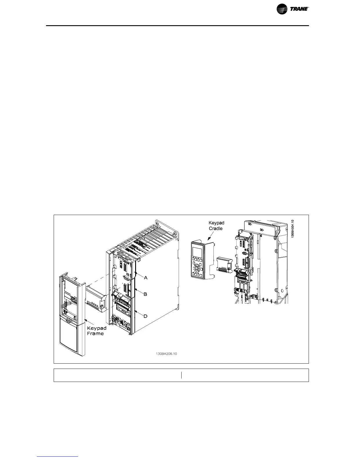
For A2, A3 and B3 enclosures:
• Remove the keypad, the terminal cover, and the keypad frame from the frequency converter.
• Fit the MCB 101 option card into slot B.
• Connect the control cables and relieve the cable by the enclosed cable strips.
Remove the knock out in the extended keypad frame delivered in the option set, so that the option
will fit under the extended keypad frame.
• Fit the extended keypad frame and terminal cover.
• Fit the keypad or blind cover in the extended keypad frame.
• Connect power to the frequency converter.
• Set up the input/output functions in the corresponding parameters, as mentioned in this document.
For A5, B1, B2, B4, C1, C2, C3, C4, D, E and F enclosures:
• Remove the keypad and the keypad cradle
• Fit the MCB 101 option card into slot B
• Connect the control cables and relieve the cable by the enclosed cable strips
• Fit the cradle
• Fit the keypad
A2, A3 and B3 enclosures A5, B1, B2, B4, C1, C2, C3, C4, D, E and F enclosures
TR200 Series VFD General Purpose I/O Option Module MCB 101 Instruction 5

 Loading...