8 18-CD20D1-18
Installer’s Guide
0
9
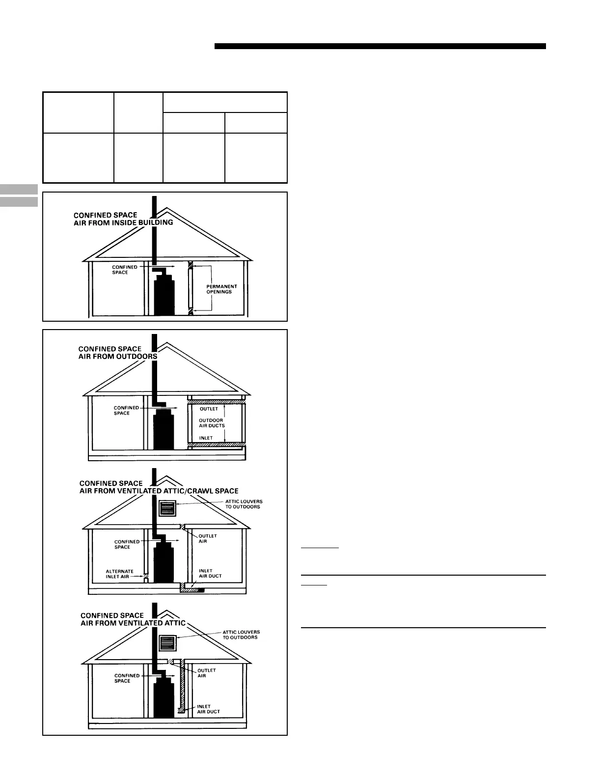
TABLE 3
MINIMUM FREE AREA IN SQUARE INCHES
EACH OPENING (FURNACE ONLY)
Furnace
Maximum
BTUH/INPUT
Rating
Air
From
Inside
Air From Outside
Vertical
Duct
Horizontal
Duct
60,000
80,000
100,000
120,000
140,000
100
100
100
120
140
15
20
25
30
35
30
40
50
60
70
DUCT CONNECTIONS
Air duct systems should be installed in accordance with
standards for air conditioning systems, National Fire Protec-
tion Association Pamphlet No. 90. They should be sized in
accordance with ACCA Manual D or whichever is applicable.
Check on controls to make certain they are correct for the
electrical supply.
Central furnaces, when used in connection with cooling units,
shall be installed in parallel or on the upstream side of the
cooling units to avoid condensation in the heating element,
unless the furnace has been specifically approved for down-
stream installation. With a parallel flow arrangement, the
dampers or other means used to control flow of air shall be
adequate to prevent chilled air from entering the furnace,
and if manually operated, must be equipped with means to
prevent operation of either unit unless the damper is in full
heat or cool position.
On any job, flexible connections of nonflammable material
may be used for return air and discharge connections to
prevent transmission of vibration. Though these units have
been specifically designed for quiet, vibration free opera-
tion, air ducts can act as sounding boards and could, if
poorly installed, amplify the slightest vibration to the
annoyance level.
When the furnace is located in a utility room adjacent to the
living area, the system should be carefully designed with
returns which minimize noise transmission through the
return air grille. Although these winter air conditioners are
designed with large blowers operating at moderate speeds,
any blower moving a high volume of air will produce audible
noise which could be objectionable when the unit is located
very close to a living area. It is often advisable to route the
return air ducts under the floor or through the attic. Such
design permits the installation of air return remote from the
living area (i.e. central hall).
When the furnace is installed so that the supply ducts carry
air circulated by the furnace to areas outside the space
containing the furnace, the return air shall also be handled
by a duct(s) sealed to the furnace and terminating outside
the space containing the furnace.
Minimum return air/“air entering” temperature for
the furnace is 55° F.
Where there is no complete return duct system, the return
connection must be run full size from the furnace to a
location outside the utility room, basement, attic, or crawl
space.
DO NOT install return air through the back of the
furnace cabinet.
RETURN AIR DUCT CONNECTION
NOTE:
On upflow 5 or 6 ton airflow models, if the airflow require-
ment exceeds 1800 CFM, these models will require return
air openings and filters on both sides; OR 1 side and the
bottom; OR just the bottom.
All return air duct systems should provide for installation of
return air filters.
1. Set the furnace in place.
2. For side return installations on upflow models, remove
the insulation around the opening in the blower
compartment.
 Loading...