Installer’s Guide
18-CD21D1-5 19
WARNING
!
FIRE OR EXPLOSION HAZARD
Failure to follow the safety warnings exactly could re-
sult in serious injury, death or property damage. Never
test for gas leaks with an open flame. Use a commer-
cially available soap solution made specifically for the
detection of leaks to check all connections. A fire or ex-
plosion may result causing property damage, personal
injury, or loss of life.
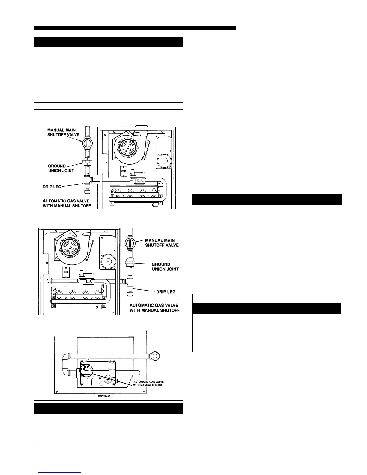
GAS PIPING
This unit is shipped standard for left side installation of
gas piping. A piping knockout is also provided in the
right side for an alternate piping arrangement. The in-
stallation of piping shall be in accordance with piping
codes and the regulations of the local gas company. Pipe
joint compound must be resistant to the chemical reac-
tion with liquefied petroleum gases.
Refer to piping Table 9 for delivery sizes. Connect gas
supply to the unit, using a ground joint union and a
manual shut-off valve as shown in Figure 24. National
codes require a condensation drip leg to be installed
ahead of the controls as shown in Figure 24.
The furnace and its individual shut-off valve must be dis-
connected from the gas supply piping system during any
pressure testing of that system at test pressures in ex-
cess of 1/2 psig.
The furnace must be isolated from the gas supply piping
by closing its individual manual shut-off valve during
any pressure testing of the gas supply piping system at
test pressures equal to or less than 1/2 psig.
CAUTION
!
Use a backup wrench on the gas valve when installing
gas piping to prevent damage to the gas valve and
manifold assembly.
NOTE:
Maximum pressure to the gas valve for natural gas is
13.8" W.C. Minimum pressure is 5.0" W.C. Maximum
pressure to the gas valve for propane is 13.8" W.C.
Minimum pressure is 11.0" W.C.
All gas fittings must be checked for leaks using a soapy
solution before lighting the furnace.
DO NOT CHECK WITH AN OPEN FLAME!
The following warning complies with State of California law, Proposition 65.
Hazardous Gases!
Exposure to fuel substances or by-products of
incomplete fuel combustion is believed by the state of
California to cause cancer, birth defects, or other
reproductive harm.
WARNING
!
SEQUENCE OF OPERATION
THERMOSTAT CALL FOR HEAT
R and W thermostat contacts close signaling the control
module to run its self-check routine. After the control
module has verified that the pressure switch contacts
are open and the limit switch(es) contacts are closed,
the draft blower will be energized.
WARNING
!
TO PREVENT AN EXPLOSION OR POSSIBLE INJURY,
DEATH AND EQUIPMENT DAMAGE, DO NOT STORE
COMBUSTIBLE MATERIALS, GASOLINE OR OTHER
FLAMMABLE VAPORS OR LIQUIDS NEAR THE UNIT.
LEFT SIDE PIPING (STANDARD)
TOP VIEW OF RIGHT SIDE PIPING
RIGHT SIDE PIPING (OPTIONAL)
f
 Loading...