14
Service Facts
X343070P08
Trouble Shooting Kit
TROUBLESHOOTING ECM-2™ MOTOR
WITH TROUBLESHOOTING CIRCUIT BOARD
AND 4 WIRE TEST CABLE
ECM-2™ TROUBLESHOOTER KIT
Order Pub. No. 34-3403-01
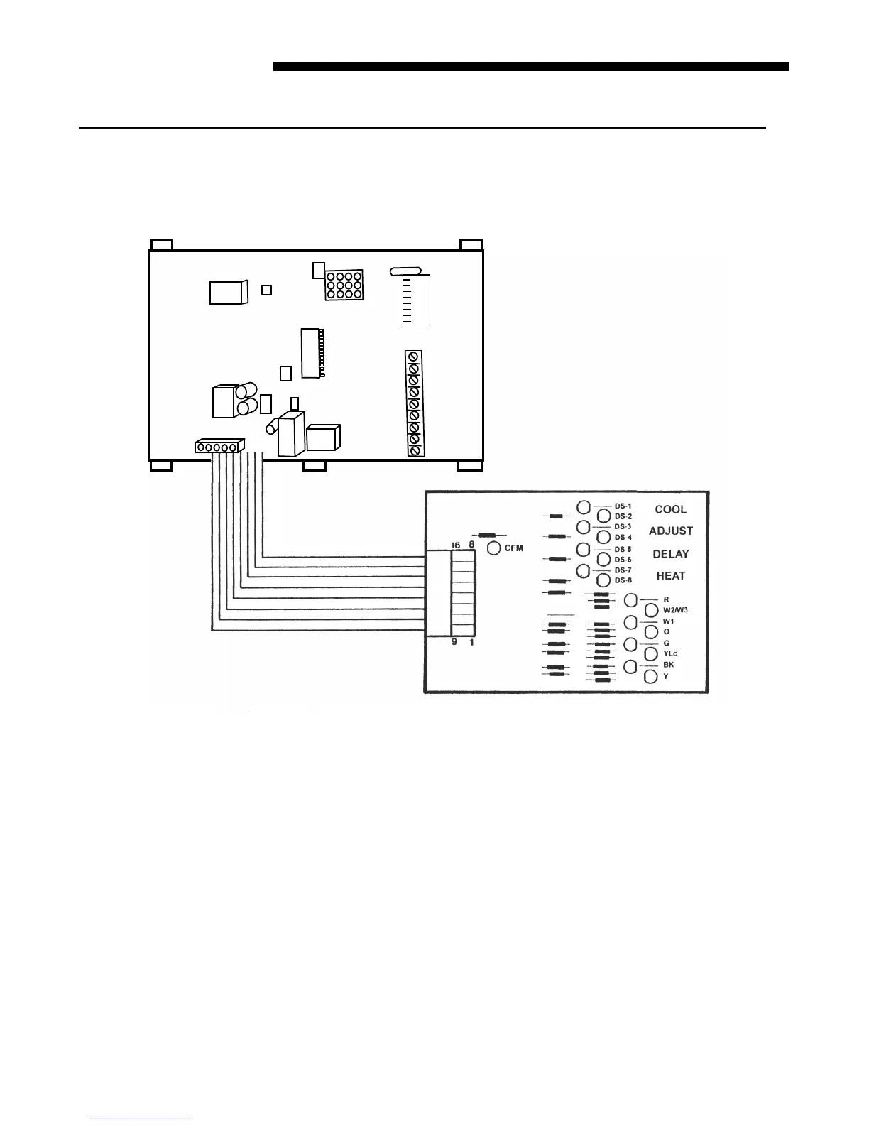
Purpose: Verify proper signals are being received by the motor control board and are being
sent to the ECM-2™ Motor by the 16 wire low voltage motor harness.
1. Turn power off
2. Disconnect all low voltage field wiring,
set all dip switches to “OFF”.
3. Disconnect the 16-pin connector at the
ECM-2™ Motor. Plug in the “Troubleshooter”
to the harness.
4. Turn on power.
5. The troubleshooter “R” L.E.D. on the board
should be on.
6. If the troubleshooter “R” L.E.D. is not
on, check for 24 volts A.C. at the motor
control board.
7. If 24 volts A.C. is not present, troubleshoot
and repair as needed.
8. If 24 volts A.C. is present, check the trouble-
shooter “R” L.E.D. and check continuity of the
16 wire cable, pin 1 to pin 1, through pin 16. If
troubleshooter “R” L.E.D. is good and 16 wire
cable pin #1 and pin #12 are good, repair or
replace motor control board.
9. The green “C.F.M.” L.E.D.’s should be
flashing on the motor control board and
troubleshooting board. If the green CFM
L.E.D. on the motor control board does not
flash, check the troubleshooter “CFM” L.E.D.
and continuity of the 16 wire harness, pin #8
and #16. If troubleshooter “CFM” L.E.D.
and harness are good, replace motor
control board.
 Loading...