BAS-SVX04C-EN • Wireless Sensors 45
Maintenance and Troubleshooting
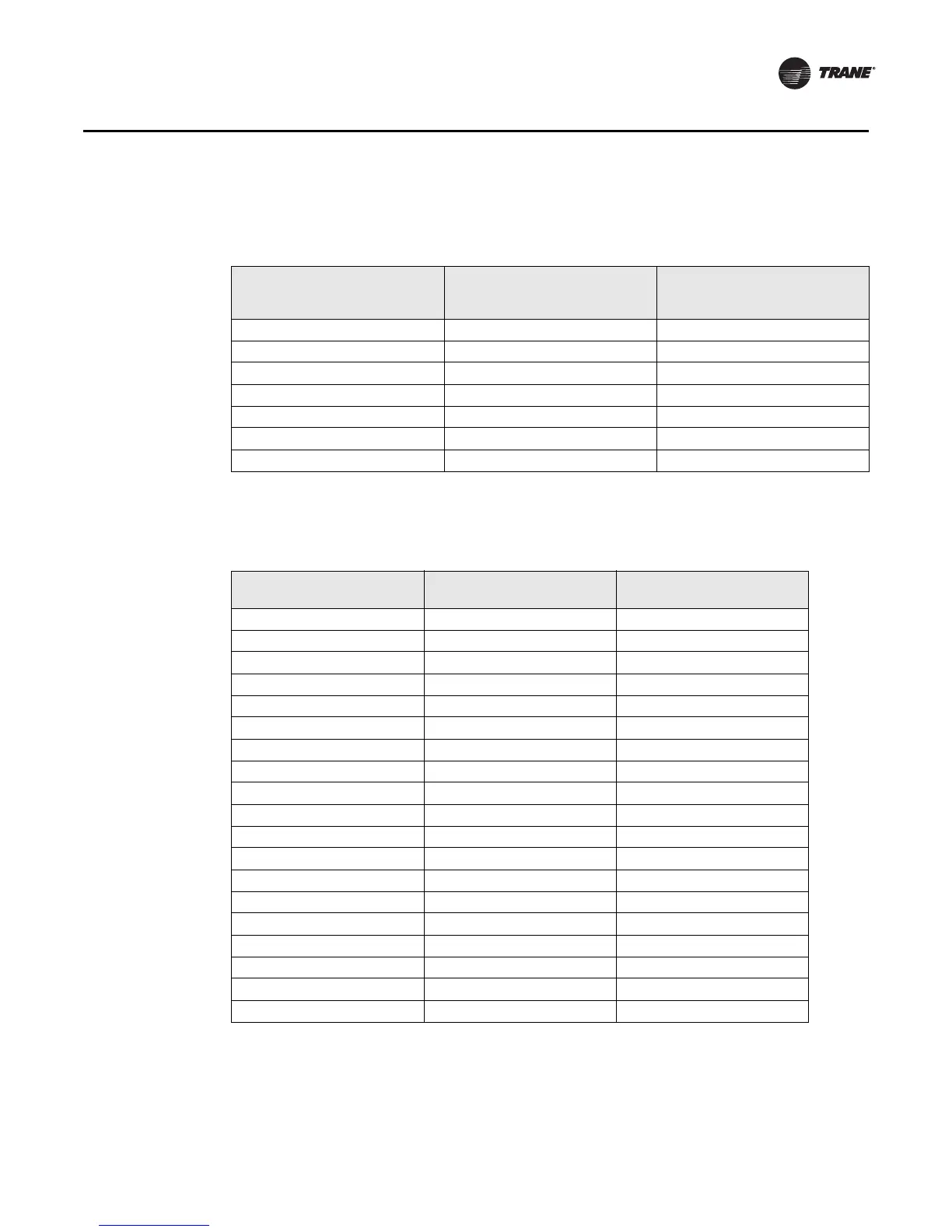
Note: The output circuits are not electrically powered; consequently, resistance can
be measured without risk of damage to the volt-ohm meter.
Table 8. Receiver resistance table for all models
Zone or setpoint
temperature
Nominal zone temperature
output resistance
Nominal setpoint and
heating setpoint output
resistance
55°F (12.8°C) 17.47 kΩ 792 Ω
60°F (15.6°C) 15.3 kΩ 695 Ω
65°F (18.3°C) 13.49 kΩ 597 Ω
70°F (21.1°C) 11.9 kΩ 500 Ω
75°F (23.9°C) 10.5 kΩ 403 Ω
80°F (26.7°C 9.3 kΩ 305 Ω
85°F (29.4°C) 8.25 kΩ 208 Ω
Table 9. Receiver resistance table for model WDS
Fan command System command
Nominal output
resistance
Auto or invalid Emergency heat 35,000 Ω
Auto or invalid Heat 19,480 Ω
Auto or invalid Auto 7680 Ω
Auto or invalid Off 2320 Ω
Auto or invalid Cool 4870 Ω
On Emergency heat 43,450 Ω
On Heat 27,930 Ω
On Auto 16,130 Ω
On Off 10,770 Ω
On Cool 13,320 Ω
High Invalid 16,130 Ω
Med Invalid 13,320 Ω
Low Invalid 10,770 Ω
Auto Invalid 2320 Ω
Off Invalid 4870 Ω
Valid Valid 7680 Ω
Invalid Valid 7680 Ω
Valid Invalid 2320 Ω
Invalid Invalid —

 Loading...