Assembly & Set-Up
3
5
Assembly
References to the right and left side of tiller are
determined from behind the equipment in the
operating position.
Recommended Tools for Assembly
• ⁄“ wrench
• Clean oil funnel
• Motor oil. Refer to the Engine Operator’s
Manual for oil specifications and quantity
required.
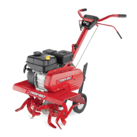
Tines
The tines must be installed correctly to insure proper
operation. See below for the proper tine installation:
1. The tines must be installed in the correct
location and the correct order. Each tine is
marked as follows:
• A1 — Inner LH Tine
• A2 — Outer LH Tine
• B1 — Inner RH Tine
• B2 — Outer RH Tine
NOTE: Images and descriptions of tine installation
are referenced from the FRONT of the tiller.
2. Use two clevis pins and two cotter pins from
the manual bag. From the FRONT of the tiller
install the inner LH tines (A1) onto the inner
left side of the shaft. Install the inner RH tines
(B1) onto the inner right side of the shaft. See
Figure 3-1.
Figure 3-1
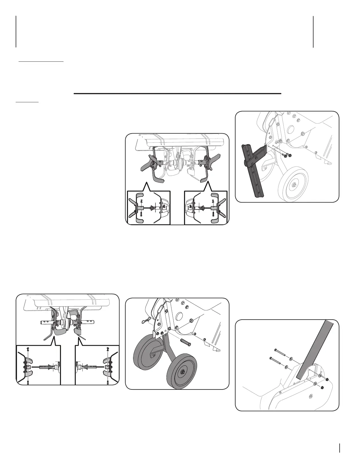
3. Use two clevis pins and two cotter pins from
the manual bag. From the FRONT of the tiller
install the outer LH tines (A2) onto the outer
left side of the shaft. Install the outer RH tines
(B2) onto the outer right side of the shaft. see
figure 3-2.
Figure 3-2
NOTE: The outer tines can be placed in either
of the two outside holes. The inner hole is for a
22” tilling width and the outer hole is for a 24”
tilling width.
Wheel Assembly & Depth Stake Assembly
1. Remove the remaining clevis pin and cotter
pin from the manual bag, install the wheel
assembly into the chain case bracket as shown
in Figure 3-3.
Figure 3-3
Contents of Carton
• One Tiller • One Handlebar Assembly • One Depth Stake Assembly
• Four Tine Assemblies • One Wheel Assembly • One Bottle of Oil
• One Operator’s Manual • One Engine Operator’s Manual
2. Remove the two screws from the bracket in
the chain case. See Figure 3-4.
Figure 3-4
3. Insert the horizontal bracket into the chain
case brackets and secure the depth stake
assembly in place with the screws just
removed in step 1. See Figure 3-4.
NOTE: The depth stake can be placed at
various positions. For setup purposes it is
suggested that the depth stake be assembled
with the stake just above or level with the
ground surface. See the Operation section for
instructions on setting the tilling depth and
adjusting the depth stake.
Handle
The handle is tilted down and packaged loose for
shipping purposes. To attach the handle, proceed as
follows:
1. Remove the bolts, washers and nuts from the
chain case bracket. See Figure 3-5.
Figure 3-5
2. Place the handle into position and secure with
the previously removed hardware. See Figure
3-5.
 Loading...