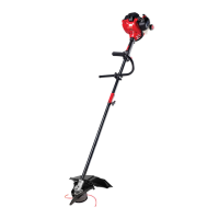
Install the cutting attachment shield when using the unit as a grass trimmer
Install the cutting attachment shield on the shield mount by inserting the three (3) screws into the
shield mount. Tighten securely with a flat blade screwdriver (Fig. 6).
REMOVE THE CUTTING ATTACHMENT AND INSTALL THE CUTTING BLADE
NOTE: To make cutting blade removal and installation easier, place the unit on the ground or on a work bench
.
Remove the Cutting Attachment Shield
See Remove and Install the Cutting Attachment Shield.
Remove the Cutting Attachment
1.
Align the shaft bushing hole with the locking rod
slot and insert the locking rod into the shaft
bushing hole (Fig. 10).
2. Hold the locking rod in place by grasping it
next to the boom of the unit (Fig. 11).
3. While holding the locking rod, remove the cutting
attachment by turning it clockwise off of the
output shaft (Fig. 12). Store the cutting attachment
for future use.
NOTE: The blade retainer under the cutting
attachment will be used when installing the
cutting blade.
3
KNOW YOUR UNIT
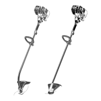
INSTALL AND ADJUST THE J-HANDLE
On some units, the J-handle may be pre-
installed. In this case, loosen the screws and
go to step 5.
1. Place the J-handle between the top and
middle clamp pieces (Fig. 1).
2. While holding the three pieces together, install
the four (4) screws through the top clamp and
into middle clamp.
NOTE: The holes in the top and middle clamp
will line up only when assembled correctly.
3. Place the clamps and the J-handle over the
shaft housing and onto the bottom clamp.
4. Hold each hex nut in the bottom clamp
recess with a finger. Start screws with a large
Phillips screwdriver. Do not tighten until you
make the handle adjustment.
5. Slide the J-handle in or out until the arrow/white
line on the decal touches the clamp assembly
(Fig. 2). You must first loosen the screws if the
handle is pre-installed.
6. While holding the unit in the operating position, position the J-handle to
the location that provides you the best grip.
7. Tighten the clamp screws evenly, until the J-handle is secure.
OPERATING THE EZ-LINK™ SYSTEM
The EZ-Link™ system enables the use of these optional Add-Ons.
Mach 4® Trimmer. . . . . . . . . . . . . . . . . . . . . . . . . . . . . . . . . . . . . . . . . . . . . . . . . . . . . . . . . . . . . . . AF720
Hedge Trimmer* . . . . . . . . . . . . . . . . . . . . . . . . . . . . . . . . . . . . . . . . . . . . . . . . . . . . . . . . . . . . . . . AH720*
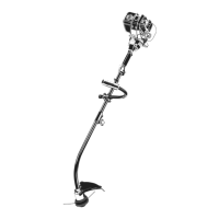
Brushcutter* . . . . . . . . . . . . . . . . . . . . . . . . . . . . . . . . . . . . . . . . . . . . . . . . . . . . . . . . . . . . . . . . . . BC720*
Cultivator . . . . . . . . . . . . . . . . . . . . . . . . . . . . . . . . . . . . . . . . . . . . . . . . . . . . . . . . . . . . . . . . . . . . GC720
Edger*. . . . . . . . . . . . . . . . . . . . . . . . . . . . . . . . . . . . . . . . . . . . . . . . . . . . . . . . . . . . . . . . . . . . . . . LE720*
Pole Saw . . . . . . . . . . . . . . . . . . . . . . . . . . . . . . . . . . . . . . . . . . . . . . . . . . . . . . . . . . . . . . . . . . . . . PS720
Straight Shaft Trimmer . . . . . . . . . . . . . . . . . . . . . . . . . . . . . . . . . . . . . . . . . . . . . . . . . . . . . . . . . . SS725
Turbo Blower . . . . . . . . . . . . . . . . . . . . . . . . . . . . . . . . . . . . . . . . . . . . . . . . . . . . . . . . . . . . . . . . . . TB720
* Do NOT use this Add-On with an electric powered unit.
REMOVING THE ADD-ON
1. Turn the knob counterclockwise to loosen
(Fig. 5).
2. Press and hold the release button (Fig. 3).
3. While firmly holding the upper shaft housing,
pull the lower shaft housing straight out of
the EZ-Link™ coupler (Fig. 4).
INSTALLING THE ADD-ON
NOTE: To make installing or removing the add-on easier, place the unit on
the ground or on a work bench.
1. Turn knob counterclockwise to loosen (Fig. 5).
2. While firmly holding the add-on, push it straight into the EZ-Link™
coupler (Fig. 4).
NOTE: Aligning the release button with the guide recess will help
installation (Fig. 3).
3. Turn the knob clockwise to tighten (Fig. 5).
For decorative trimming/edging with the line cutting head, lock the release button into the 90° hole (Fig. 5).
ASSEMBLY INSTRUCTIONS
WARNING:
To prevent serious personal injury, never operate the trimmer without the cutting
a
ttachment shield in place.
Guide Recess
Fig. 3
Release
Button
EZ-Link™ Coupler
Upper Shaft
Housing
Fig. 4
Lower Shaft
Housing
Primary Hole
Knob
Fig. 5
90˚ Edging Hole
(Trimmer Only)
A
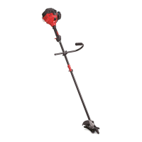
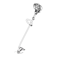
PPLICATIONS
As a trimmer:
• Cutting grass and light weeds.
• Edging
• Decorative trimming around trees,
fences, etc.
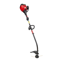
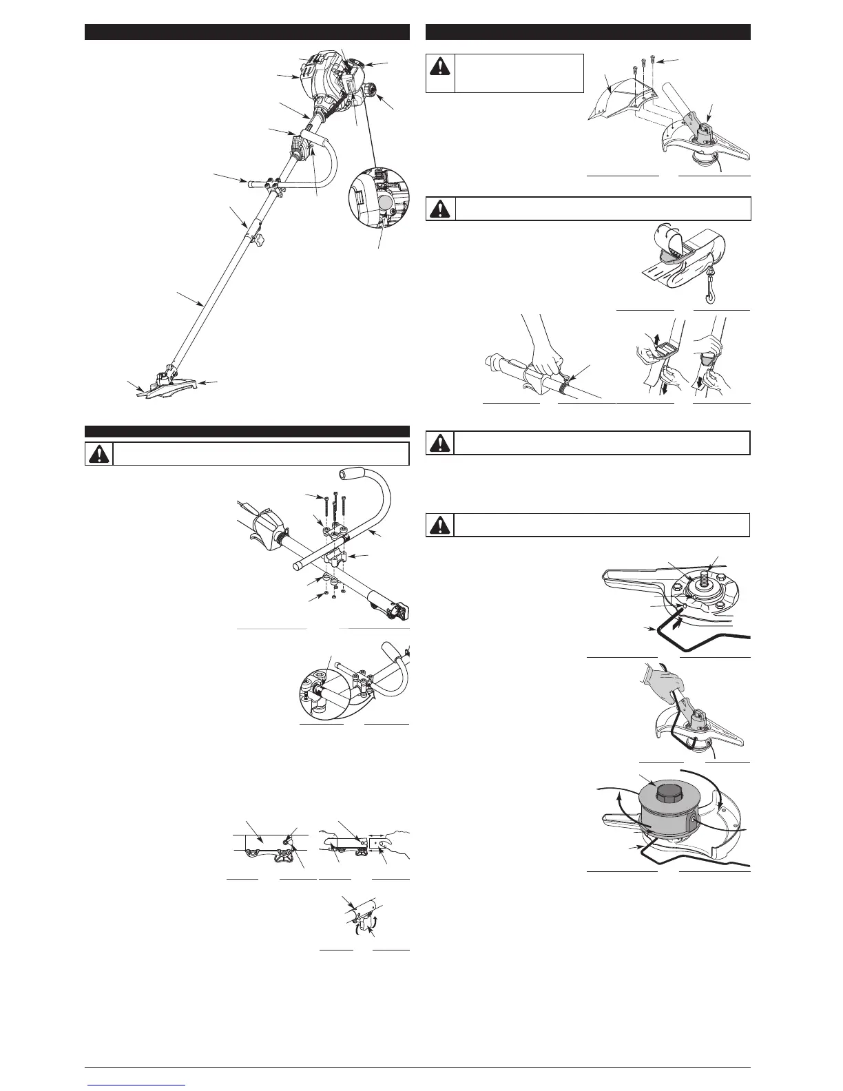
Throttle
Control
J-Handle
Shaft Grip
S
park Plug
Shaft Housing
Starter
Rope
Grip
M
uffler
On/Off Control
Cutting Head
Cutting Head Shield
F
uel Cap
Choke Lever
P
rimer Bulb
EZ-Link™
A
ir Filter
C
over
ASSEMBLY TOOLS REQUIRED
•
Phillips screwdriver
REMOVE AND INSTALL THE CUTTING ATTACHMENT SHIELD
Remove the cutting attachment shield when
using the unit as a brushcutter
Remove the cutting attachment shield from the
shield mount by removing the three (3) screws with
a flat blade screwdriver (Fig. 6). Store parts for
future use.
ASSEMBLY INSTRUCTIONS
WARNING:
The cutting attachment
s
hield should NOT be installed when
o
perating the unit with a blade. Remove the
c
utting attachment shield before removing
or installing the blade.
C
utting
Attachment
Shield
Screws (3)
G
ear Housing
F
i
g
.
6
WARNING:
T
o avoid serious personal injury, the cutting attachment shield MUST be in place at all
t
imes while operating the unit as a grass trimmer.
WARNING:
T
he gear housing gets hot with use. It can result in injury to the operator. The housing remains
hot for a short time even after the unit is turned off. Do not touch the gear housing until it has cooled.
T
op
C
l
am
p
J
-
H
an
dl
e
M
i
ddl
e
C
l
am
p
B
ot
t
om
C
l
am
p
N
u
t
s
(
4
)
S
crew
s
(
4
)
F
i
g.
1
D
ecal
Fig. 2
Fig. 12
Cutting Attachment
Locking Rod
Slot
Locking Rod
Shaft Bushing Hole
Output Shaft
Output Shaft Bushing
Locking Rod
S
lot
L
ocking Rod
Fig. 11
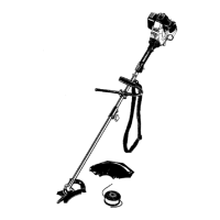
INSTALL THE HARNESS
1. Push the strap through the center of the buckle.
2. Pull the strap over the cross bar and down through the
slot in the buckle (Fig. 7).
3. Put the harness on over head and onto shoulder. Snap it
on to the support fitting (Fig. 8).
4. Adjust length to fit the operator’s size. Pull tab to
lengthen, pull strap to shorten (Fig. 9).
WARNING:
Always use the shoulder harness when using the cutting blade to avoid
serious personal injury.
F
ig. 7
S
upport
F
itting
F
ig. 8
F
ig. 9
F
ig. 10
 Loading...