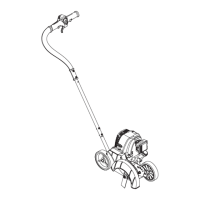
EDGERBLADEREPLACEMENT
WARN!NG: To avoid Serious personal injuryl
always wear gloves while handling, removing
or nsta ng the bade.
A WARNING: The gear housing gets hot after long
periods of use. To avoid serious personal injury,
do not touch the hous ng unt t has coo ed.
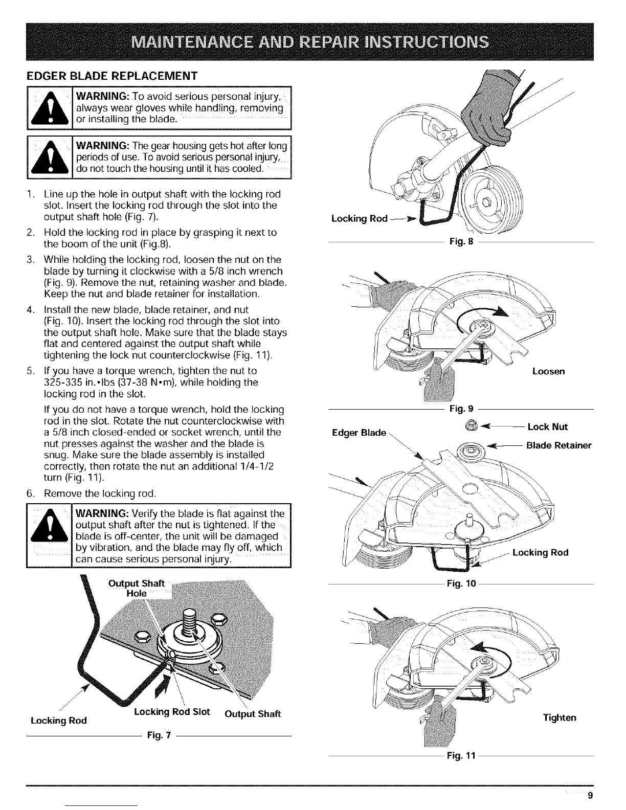
1. Line up the hole in output shaft with the locking rod
slot. Insert the locking rod through the slot into the
output shaft hole (Fig. 7).
2. Hold the locking rod in place by grasping it next to
the boom of the unit (Fig.8).
3. While holding the locking rod, loosen the nut on the
blade by turning it clockwise with a 5/8 inch wrench
(Fig. 9). Remove the nut, retaining washer and blade.
Keep the nut and blade retainer for installation.
4. Install the new blade, blade retainer, and nut
(Fig. 10). Insert the locking rod through the slot into
the output shaft hole. Make sure that the blade stays
flat and centered against the output shaft while
tightening the lock nut counterclockwise (Fig. 11).
5. If you have a torque wrench, tighten the nut to
325-335 in.-Ibs (37-38 N-m), while holding the
locking rod in the slot.
If you do not have a torque wrench, hold the locking
rod in the slot. Rotate the nut counterclockwise with
a 5/8 inch closed-ended or socket wrench, until the
nut presses against the washer and the blade is
snug. Make sure the blade assembly is installed
correctly, then rotate the nut an additional 1/4-1/2
turn (Fig. 11).
6. Remove the locking rod.
_ WARNING: Verify the blade is flat against the I
output shaft after the nut is tightened. If the I
blade is off-center, the unit will be damaged I
by vibration, and the blade may fly off, which
can cause serous persona njury.
Output Shaft
Hole
\
LockingRod Slot Output Shaft
LockingRod
Fig. 7
Locking Rod
Edger Blade\
Fig. 8
Loosen
Fig. 9
_ Lock Nut
Blade Retainer
/Locking Rod
Fig. 10
Tighten
Fig. 11
9
 Loading...