Assembly Instructions
2
TREADMILLS
NOTE: Treadmill Wiring Schematic is available on page 5.
1. Using 8 inch Wire Ties (d), install Auxiliary Power Supply per Treadmill Frame Assembly
Instructions shipped with treadmill. NOTE: 220V treadmills come equipped with the Auxiliary
Power Supply already installed.
2. Place a piece of cardboard or towel on top of Fan Housing (Console Rack for LC1100 model)
for protection.
3. Gently place display on protected Fan Housing, or Console Rack, while still continuing to hold
display.
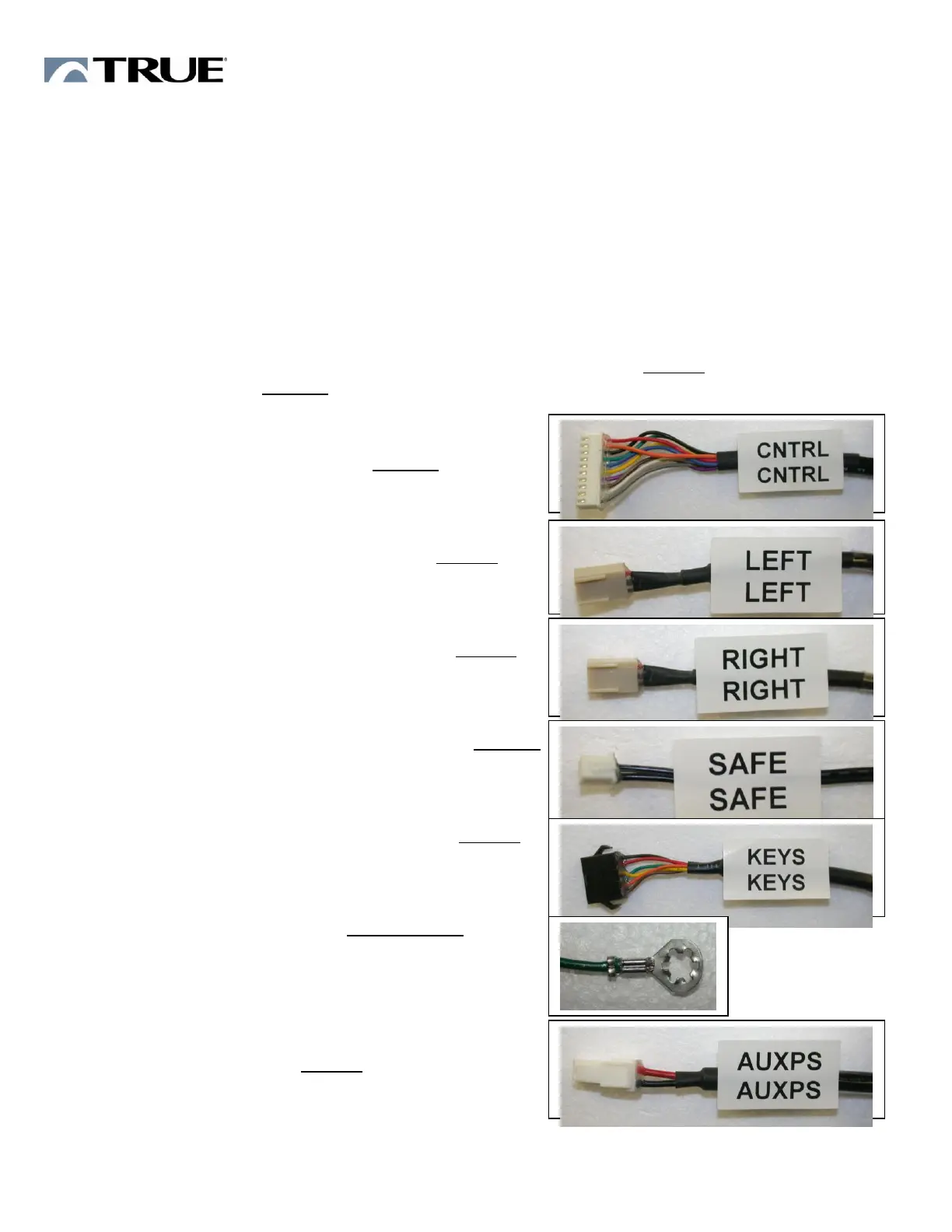
4. Firmly hold display. Using the DISPLAY CONNECTION DIAGRAM-TREADMILL, connect the
following 9 Console Rack cables to their mating cable (indicated by CABLE), or connector on the
Display (indicated by BOARD).
1 CNTRL Control Cable – BOARD
10-pin connector is polarized. Insert properly.
2 LEFT Contact Heart Rate Cable - CABLE
3-Pin connectors are polarized. Insert properly.
3 RIGHT Contact Heart Rate Cable - CABLE
3-Pin connectors are polarized. Insert properly.
4 SAFE Cable (Safety key)–black wires-BOARD
2-pin connector is polarized. Insert properly.
5 KEYS Cable (Center Pod Keypad) - CABLE
6-pin connector is polarized. Insert properly.
6 GND Display Ground – Console Rack
See Fig 1 on next page of GND screw location.
Position Ground lug pointing up so that it does
not interfere with the Display attachment.
7 AUXPS Cable - CABLE
(DC Power Supply to display)
2-pin connector is polarized. Insert properly.

 Loading...