Page 2 of 10 TFP1112_EN
Operation
The Inlet Chamber of the Accelerator, Fig‑
ure 1, is pressurized via its connection to
the system (at a point above the maximum
expected level of drain back water). The Pi‑
lot Chamber is, in turn, pressurized through
its inlet port which is formed by the annular
opening around the lower tip of the Anti‑
Flood Valve. As the Pilot Chamber increases
in pressure, the Dierential Chamber is
pressurized through the Restriction.
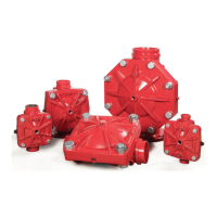
The Accelerator is in its set position while it
is being pressurized as well as after the In‑
let, Pilot Chamber and Dierential Chamber
pressures have equalized. When in the Set
position, the Outlet Chamber is sealed o
by the Exhaust Valve which is held against
its seat by a combination of the Spring
pushing up against the Lever and the net
downward force exerted by the pressure in
the Pilot Chamber.
Both small and slow changes in system pres‑
sure are accommodated by ow through
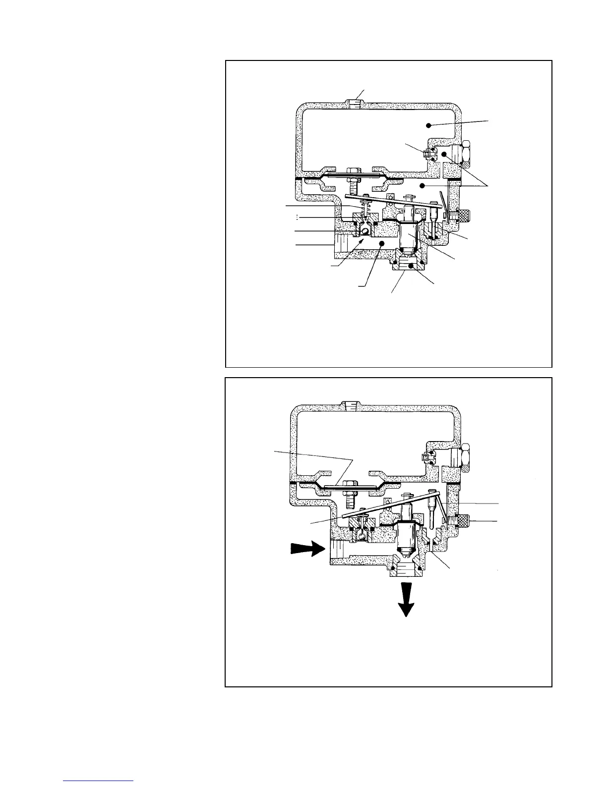
the Restriction. When, however, there is a
rapid and steady drop in system (i.e., Inlet
and Pilot Chamber) pressure, the pressure
in the Dierential Chamber reduces at a
substantially lower rate. This condition cre‑
ates a net downward force on the Plunger
which rotates the Lever. As the Lever is ro‑
tated, Figure 2, the Relief Valve is raised out
of the Relief Port and the Anti‑Flood Valve is
depressed downward into the Pilot Cham‑
ber Inlet Port, venting the Pilot Chamber.
The system pressure in the Inlet Chamber
then forces (raises) the Exhaust Valve o its
seat. This continues the rotation of the Le‑
ver into the tripped (latched) position, Fig‑
ure 2. As the Exhaust Valve is raised o its
seat, system pressure is transmitted to the
intermediate chamber of the dry pipe valve
which neutralizes the dierential pressure
holding the valve closed.
Following the dry pipe valve trip, major wa‑
ter borne debris is prevented from entering
the Accelerator (via the connection to the
system piping) by the Strainer located at its
Inlet. Water and any ne water borne debris
such as silt is prevented from entering the
Pilot Chamber by virtue of the Anti‑Flood
Valve having sealed o its inlet port. The
Check Valve located downstream of the Ac‑
celerator Outlet prevents any water borne
debris from entering the Accelerator via the
connection to the intermediate chamber of
the dry pipe valve.
After the accelerator/dry pipe valve has
tripped and the sprinkler system has been
drained, the piping from the system to the
Accelerator must also be drained and the
Operat ion
The Inlet Chamber of the Accelerator,
Figure 1, is pressurized via its connec-
tion to the system (at a point above the
maximum expected level of drain back
water). The Pilot Chamber is, in turn,
pressurized through its inlet port which
is formed by the annular opening
around the lower tip of the Anti-Flood
Valve. As the Pilot Chamber increases
in pressure, the Differential Chamber
is pressurized through the Restriction.
The Accelerator is in its set position
while it is being pressurized as well as
after the Inlet, Pilot Chamber and Dif-
ferential Chamber pressures have
equalized. When in the Set position,
the Outlet Chamber is sealed off by the
Exhaust Valve which is held against its
seat by a combination of the Spring
pushing up against the Lever and the
net downward force exerted by the
pressure in the Pilot Chamber.
Both small and slow changes in sys-
tem pressure are accommodated by
flow through the Restriction. When,
however, there is a rapid and steady
drop in system (i.e., Inlet and Pilot
Chamber) pressure, the pressure in
the Differential Chamber reduces at a
substantially lower rate. This condition
creates a net downward force on the
Plunger which rotates the Lever. As the
Lever is rotated, Figure 2, the Relief
Valve is raised out of the Relief Port
and the Anti-Flood Valve is depressed
downward into the Pilot Chamber Inlet
Port, venting the Pilot Chamber.
The system pressure in the Inlet
Chamber then forces (raises) the Ex-
haust Valve off its seat. This continues
the rotation of the Lever into the
tripped (latched) position, Figure 2. As
the Exhaust Valve is raised off its seat,
system pressure is transmitted to the
intermediate chamber of the dry pipe
valve which neutralizes the differential
pressure holding the valve closed.
Following the dry pipe valve trip, major
water borne debris is prevented from
entering the Accelerator (via the con-
nection to the system piping) by the
Strainer located at its Inlet. Water and
any fine water borne debris such as silt
is prevented from entering the Pilot
Chamber by virtue of the Anti-Flood
Valve having sealed off its inlet port.
The Check Valve located downstream
of the Accelerator Outlet prevents any
water borne debris from entering the
Accelerator via the connection to the
intermediate chamber of the dry pipe
valve.
After the accelerator/dry pipe valve
has tripped and the sprinkler system
has been drained, the piping from the
FIGURE 1
MODEL ACC-1 ACCELERATOR IN SET POSITION
FIGURE 2
MODEL ACC-1 ACCELERATOR IN TR IPPED POSITION
Page 2 of 8
TFP1112
FIGURE 1
MODEL ACC‑1 ACCELERATOR IN SET POSITION
FIGURE 2
MODEL ACC‑1 ACCELERATOR IN TRIPPED POSITION
1/4” NPT GAUGE
CONNECTION
RESTRICTION
SPRING
ANTI‑FLOOD VALVE
BALL FLOAT
1/2” NPT INLET
PILOT CHAMBER
INLET PORT
INLET CHAMBER
1/2” NPT OUTLET
OUTLET CHAMBER
EXHAUST VALVE
RELIEF VALVE
PILOT CHAMBER
DIFFERENTIAL
CHAMBER
PLUNGER
LEVER
FROM SYSTEM
PIPING
TO DRY PIPE VALVE
INTERMEDIATE
CHAMBER
RELIEF PORT
RESET KNOB
LATCH
 Loading...