as well as during inspections, to make certain that the
Automatic Drain Valve is open.
When one or more automatic sprinklers operate in re-
sponse to a fire, air pressure within the system piping is
relieved. When the air pressure becomes sufficiently re-
duced, the water pressure overcomes the differential hold-
ing the Clapper Assembly closed and the Clapper Assem-
bly swings clear of the water seat to permit waterflow into
the system piping and subsequently to be discharged
from any open sprinklers.
Under full flow conditions, the Clapper Assembly will
open as shown in Figure 2-B. Also, with the Clapper As-
sembly open, the intermediate chamber is pressurized
and water flows through the alarm port at the rear of the
Model A-1 Dry Pipe Valve to actuate system waterflow
alarms. The flow from the alarm port is also sufficient to
close the otherwise normally open Automatic Drain Valve
(5 - Fig. 4).
As an option, the Model A-1 Dry Pipe Valve may be
equipped with a Model S430 Dry Pipe Valve Accelerator
to reduce the time for the Dry Pipe Valve to open follow-
ing the operation of one or more automatic sprinklers,
and in some cases may be required to meet the require-
ments of NFPA 13 for systems having a capacity greater
than 500 gallons (1890 litres). Refer to Figure 7 and Prod-
uct Data Sheet 2-5.4.10.
DESIGN CRITERIA
The Model A-1 Dry Pipe Valve must be installed vertically
as shown in Figure 6, and it must be installed in a readily
visible and accessible location, where the valve and asso-
ciated trim must be maintained at a minimum tempera-
ture of 40°F/4°C.
NOTE
Heat tracing of the Model A-1 Valve or its associated trim
is not permitted. Heat tracing can result in the formation
of hardened mineral deposits which are capable of pre-
venting proper operation.
In planning the installation, consideration must also be
given to the disposal of the large quantities of water
which may be associated with draining the system, per-
forming a flow test, or performing a system trip test.
Installation configuration and clearance dimensions are
given in Figure 6. The flanged inlet connection is faced
and drilled per ANSI Standard B16.1, unless otherwise
specified when ordered.
Review the requirements of NFPA 13 with respect to the
requirements for quick opening devices (Model S430 Dry
Pipe Valve Accelerator), air compressor sizing, waterflow
alarms, and low pressure alarm switches.
STAR SPRINKLER INC.
Page 2
2-2.1.31
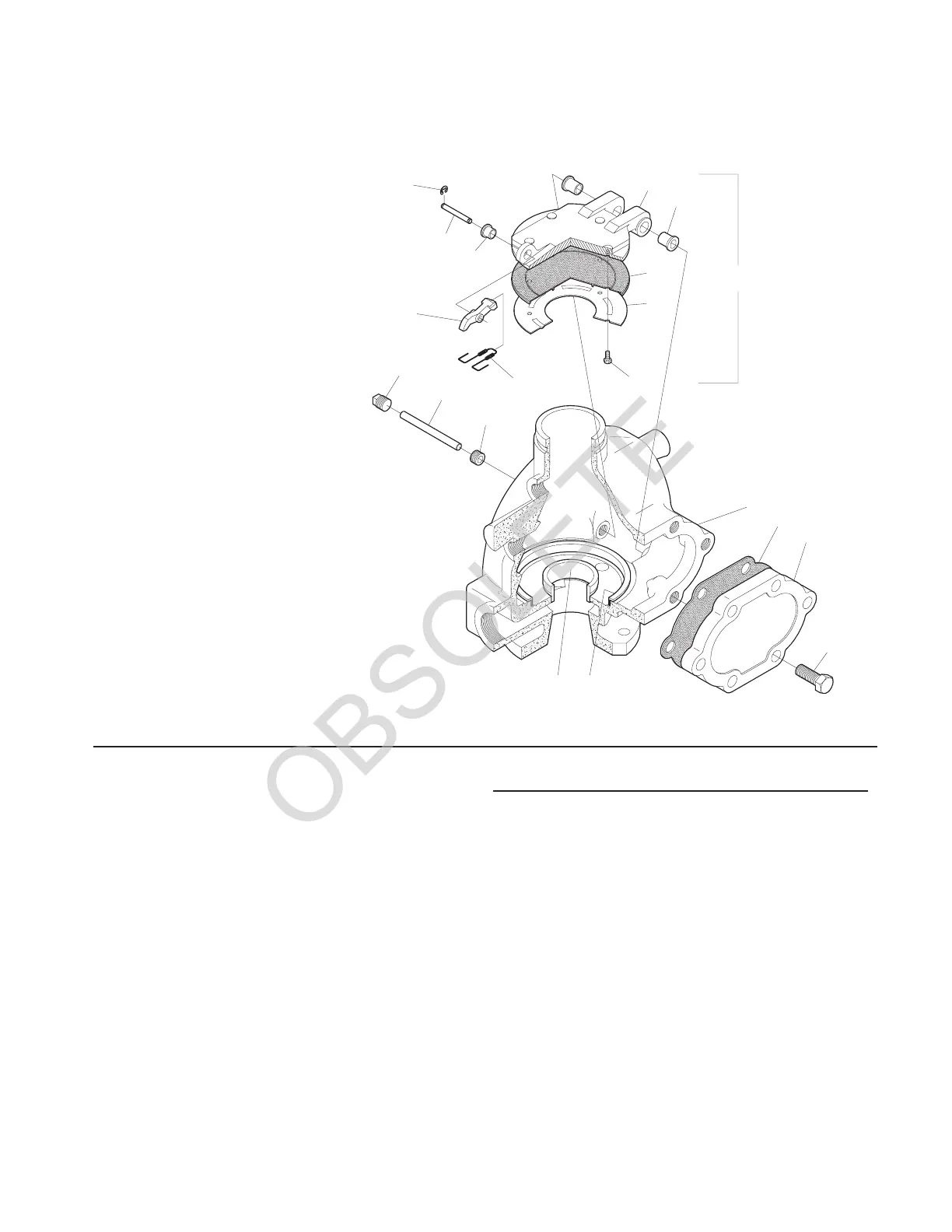
FIGURE 1
4 INCH (DN100) MODEL A-1
DRYPIPEVALVE
ASSEMBLY
1
5
4
CLAPPER
ASSEMBLY
9
8
7
19
18
16
17
11
10
12
13
15
14
32
6
NO. DESCRIPTION....QTY. PART
1 Body .......... 1 NR
2 WaterSeatRing.... 1 NR
3 AirSeatRing...... 1 NR
4 Handhole Cover .... 1 400-02-000
5 Handhole Cover Gasket 1 400-04-000
6 Handhole Cover Bolt,
3/4-10UNCx2" .... 6 600-03-000
7 Clapper ......... 1 400-182-00
8 Clapper Facing ..... 1 400-191-00
9 Clapper Facing
Retainer ........ 1 400-190-00
10 Clapper Facing
RetainerBolts ..... 5 600-80-000
11 Clapper Latch ..... 1 300-10-000
12 Clapper Latch Spring . 1 300-21-000
13 Clapper Latch
HingePin........ 1 300-23-000
14 Clapper Latch
Hinge Pin
RetainingRing..... 2 300-22-000
15 Clapper Latch
Hinge Pin Bushing . . . 2 818-08-000
16 Clapper Hinge Pin . . . 1 8010-10-20
17 Body
Bushing......... 2 600-187-01
18 Clapper Hinge Pin
Plug,1/2"NPT..... 2 8010-12-00
19 Clapper Hinge Pin
Clapper Bushing .... 2 8010-08-00
— Clapper Assembly . . . 1 400-186-00
NR — Not Replaceable
 Loading...


