
D
David HayesAug 6, 2025
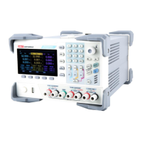
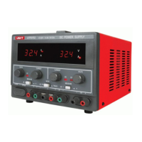
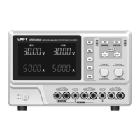
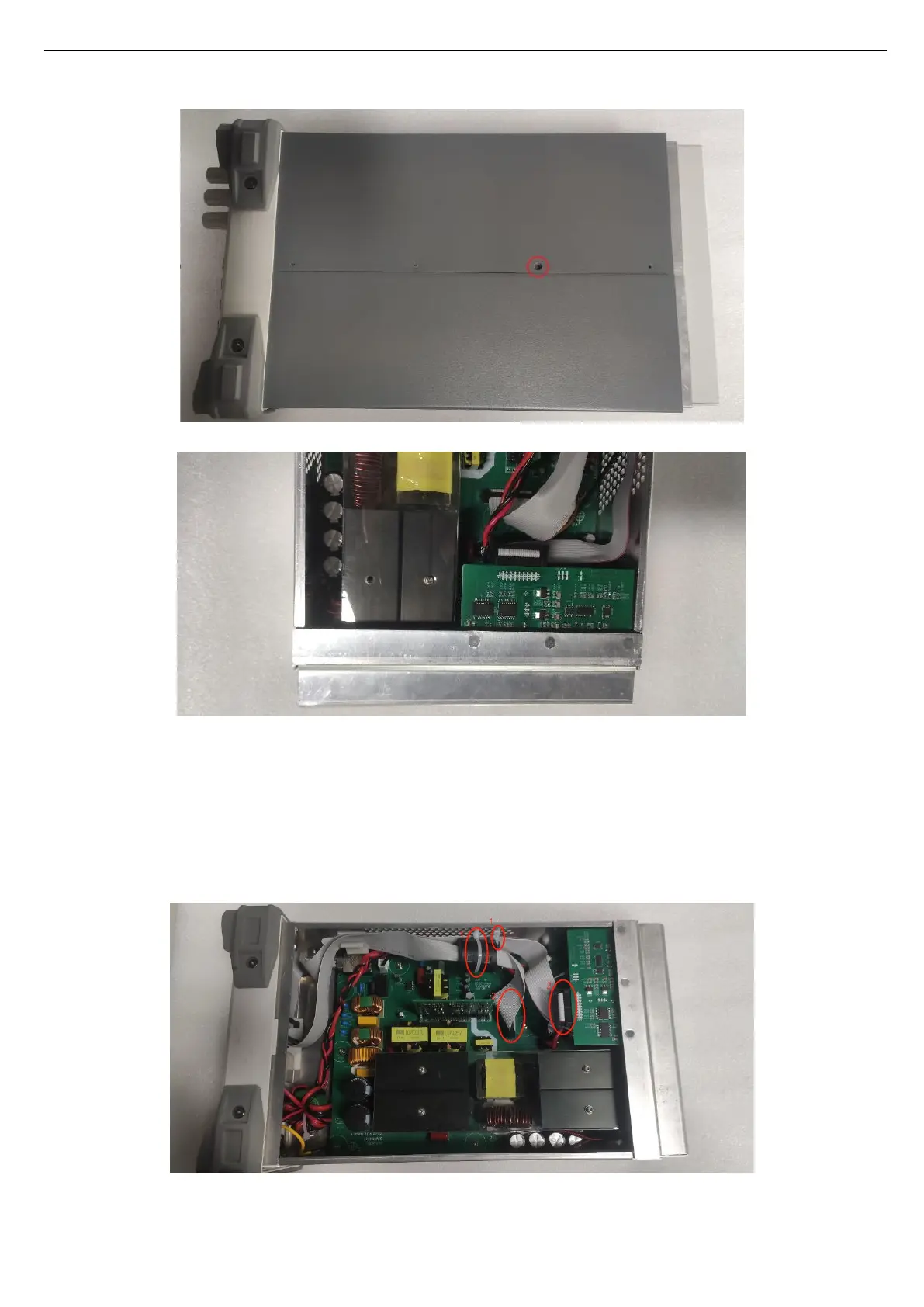
What to do if my UNI-T UDP6900 cannot power on?
- SscottashleyAug 6, 2025
If your UNI-T Power Supply doesn't power on, first ensure the power cable is properly connected. If the problem persists, check the fuse and replace it if it's blown. If neither of these solutions work, the power module may be faulty.