Service Manual UDP6900 Series Digital Control Power Supply
Instruments.uni-trend.com 22 / 29
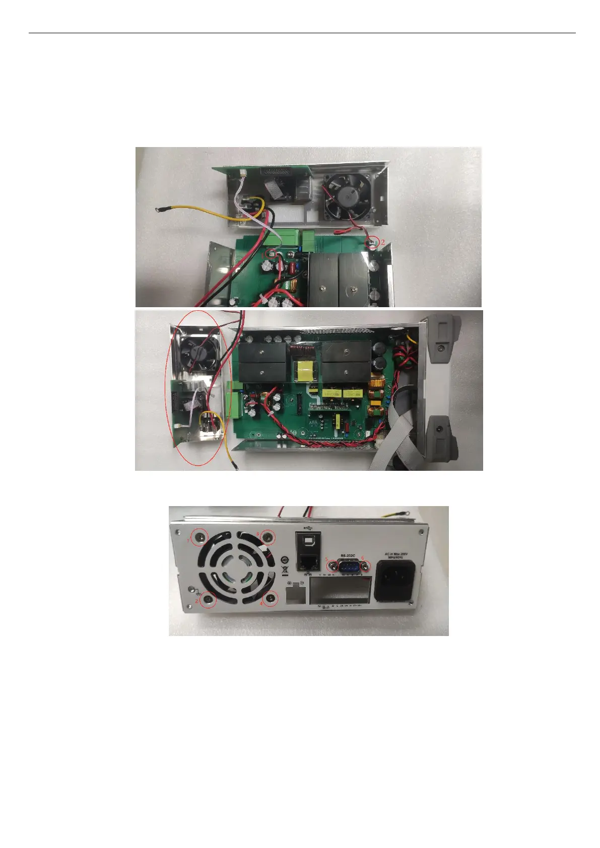
4. Pull out the double-head wiring and fan wiring on the PCB (note: the terminal on the PCB should be held
down first, and then pull out the wire to prevent the terminal from being pulled off. This method is used
for similar interfaces in the following, such as removing the fan wire interface and panel wire interface
in the surface cover.) The rear cover can be removed as shown in the following figure.
5. Disassemble the rear components — RS232 and fan, remove 6 screws, as shown in the following figure.
6. Remove 3 screws securing the rear cover, pull out the RS232 wiring interface, as shown in the
following figure.
 Loading...