Service Manual UDP6900 Series Digital Control Power Supply
Instruments.uni-trend.com 25 / 29
4. Push outward slightly, shake the front cover up and down slightly in a small amplitude, and remove the
front cover modules (during the process, pay attention not to shake too much, resulting in breakage of
the switch button.)
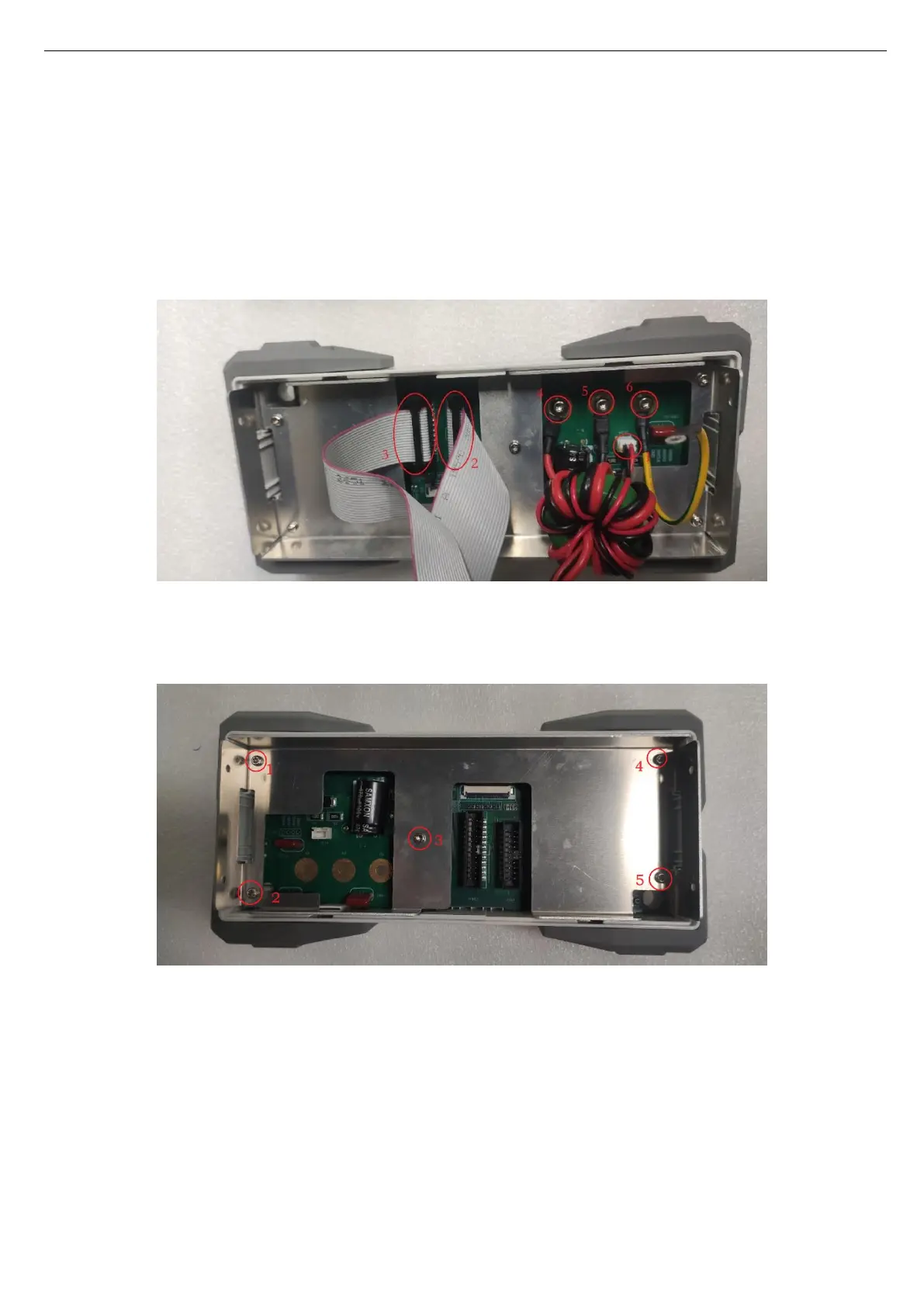
5. Pull out the signal wiring and wire socket of front cover on the PCB, use T20 quincunx screwdriver to
remove 3 screws securing the front cover wiring to move the front panel, as shown in the following
figure.
6. Use T10 quincunx screwdriver to remove 5 screws securing the front panel, as shown in the following
figure.
7. Press the screen buckle upward to remove the screen interface, and then use T6 quincunx screwdriver
to remove 9 screws on the PCB, as shown in the following figure.
 Loading...